

 EN
EN
 AR
AR CS
CS DA
DA NL
NL FI
FI FR
FR DE
DE EL
EL IT
IT JA
JA KO
KO NO
NO PL
PL PT
PT RO
RO RU
RU ES
ES SV
SV TL
TL IW
IW ID
ID LV
LV SR
SR SK
SK VI
VI HU
HU MT
MT TH
TH TR
TR FA
FA MS
MS GA
GA CY
CY IS
IS KA
KA UR
UR LA
LA TA
TA MY
MY
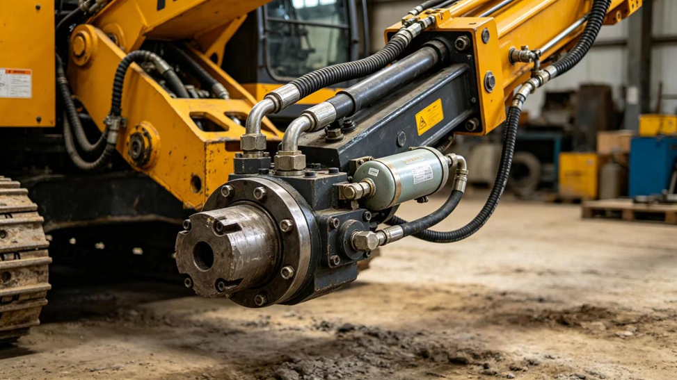
Mae cilgerrig hydrolig yn dibynio ar gydran fach, sydd yn cael ei anwybyddu yn aml, i gadw'r system taro'n glir a chyffredinol: y cyflwr cylchrediad diaphragm . Pan fo'n gweithio'n iawn, nid oes angen i'r rhan fwyaf o weithwyr feddwl am ddim. Pan fo'n methu, mae'r egni taro'n gostwng, mae sain y cilgerrig yn newid, ac yn dirwyn ar brodwriaeth y rig. Mae'r erthyliad hwn yn egluro sut mae'r cyflwr cylchrediad a'i ddiaphragm yn gweithio o fewn cilgerrig hydrolig, sut i adnabod arwyddion methiant y diaphragm, a beth i'w wirio cyn archebu amgen.
Beth yw Cyflwr Cylchrediad mewn Cilgerrig Hydrolig?
Mae cyflwynydd yn gynhwysydd bychan pwysedd a adeiladwyd i fewn i gylchred tarwio hydrolig. O fewn y cynhwysydd, mae diaphragm hyblyg — a elwir weithiau'n dal i gael ei leoli fel "cwp lledr" mewn catalogau rhannau hen, sydd yn adferiad o enwau cynharach ar ddiaphragmau — yn rhannu dau ghamrau: un sydd wedi'i llenwi â nitrôgen tanwyllt, a'r llall sydd wedi'i gysylltu â chylchred olew hydrolig y tarw. Oherwydd bod y ochr nitrôgen yn cael ei glosio ac yn cael ei reoli cyn gosod y cyflwynydd, ac mae'r ochr olew yn agored i'r cylchred hydrolig gweithredol, gelwir y cydran yn aml yn gyflwynydd nitrôgen neu gyflwynydd nwy.
Defnyddir cyflwynydd hydrolig ar ochr uchel-bwysedd o gylchred tarw gan y rhan fwyaf o dorriadau creadigol hydrolig, ac mae llawer o ddyluniadau yn ychwanegu ail gyflwynydd is-bwysedd yn y gylchred adferiad neu'r gylchred ffyrdd. Mae'r ddau yn gweithio ar yr un egwyddor sylfaenol er eu bod yn wahanol o ran eu rheoli pwysedd a'u swyddogaeth.
Mae llenyddiaeth peirianneg hydrolig yn grwpio cyrraeddwrion yn gyffredinol i mewn i dri theulu: math fwlch (sac), math diaphragm, a math piston. Mae'r cymharfryd cyhoeddedig rhwng y tri yn nodi bod cyrraeddwrion piston yn gallu cynghori amrediad eithaf eang o gyfaint a phwysau heb fod yn cyfyngedig gan gymhareb cywasgu elastomer, ond mae mass y piston yn rhoi ateb dynameg sydd yn sylwadwy'n llai cyflym na chyrraeddwrion bwlch neu diaphragm, sy'n gwneud mathau piston yn anaddas i gynnwys pwlsoedd bychain, cyflym ar bwysau isel, er eu bod yn gallu perfformio'n dda unwaith y bydd pwysau gweithredu yn uchel iawn i wneud anertiad y piston yn llai sylwadwy. Yn yr un modd, mae cyrraeddwrion bwlch a diaphragm yn cynnwys mass symleiddiedig o bethau sydd yn symud ac yn ymateb yn gyflym i newidiadau cyflym yn y pwysau, sydd yn union yr ymadrodd sydd ei angen ar gylchedd percwswn — un rheswm ymarferol pam mae cyrraeddwrion offerynnau glanu carreg a chyrraeddwrion torrwr hydrolig yn cael eu hadeiladu yn bennaf fel mathau diaphragm neu bwlch yn hytrach na mathau piston.
Sut mae’r diaffragm cyrraeddol yn gweithio wrth dorri?
Mae swydd y diaffragm yn symud. Wrth i bwysedd olew yn y cylch torri cynyddu yn ystod pob cylch torri, mae'r hylif hydrolig yn pwshio yn erbyn y diaffragm, gan ei wneyddo tuag at y ochr nwy a'u cywasgu'r nitrogen ar ôl iddo. Pan mae'r pwysedd yn y cylch yn gostwng eto, mae'r nwy cywasgiedig yn ehangu a phwshio'r diaffragm yn ôl, gan orfodi'r olew allan o'r cyrraeddwr a'i hanfon i'r cylch. Mae'r symudiad rhwng-dro hwn, a ddisgrifir yn llenyddiaeth peirianneg fel symudiad 'troi' y diaffragm, yn dilyn y berthnaseb cyffredinol rhwng pwysedd a chyfaint yn y gyfraith gas: wrth i'r cawell olew tyfu, mae'r cawell nwy'n taro a'u pwysedd yn codi, ac eisoes.
Mwy penodol, mae'r llwyth nitrogen yn dilyn y gyfraith gas polytropig a ddefnyddir yn ym mhob darn o lenyddiaeth gynllunio cyrraeddwr:
p · V n = p 0· V 0n = cyson (1)
ble mae p a V yn hwy pressure a chyfaint y nwy ar unrhyw funud, mae p₀ a V₀ yn y pwysedd cyn-lanlwyddo a'r cyfaint, ac mae n yn mynegai polytropig. Fel arfer, mae astudiaethau modelu hydrolig o systemau sydd â chynhwysyddion yn trin cylchoedd araf o lanlwyddo a dadlanlwyddo (hwy na thri eiliad) fel bodent bron yn isothermaidd, gyda n agos at 1, ac yn trin cylchoedd cyflym (dan amheu o dri eiliad) fel bodent bron yn adiabataidd, gyda n agos at 1.4. Mae cylch percwsiau drill craig yn ailadrodd nifer fawr o weithiau pob eiliad, felly mae cywasgu'r nwy o fewn ei chynhwysydd yn sefyll yn gryfach yn y rheoliad cyflym, adiabataidd yn hytrach na pherfformio fel y rhagdybiaeth isothermaidd araf a ddefnyddir weithiau mewn esboniadau symlified.
Mae hyn hefyd yn golygu nad yw'r diaphragm a'i gwaith nwy yn ymddwyn fel cwlwm syml sefydlog; mae gwaith modelu ar ddynameg cyrraedd yn cynrychioli'r ochr nwy fel system cwlwm-a-dampiwr, gyda chryfder nwy a term dampiwr sydd yn dibynu ar y pwysau gweithrediad a'r cyfaint ar y munud hwnnw. Yn yr ymarfer, nid dim ond faint y gall y diaphragm ystwyro, ond hefyd mor gyflym a phur y gall y diaphragm olrhain newid pwysau sydd yn pennu a yw'r cyrraedd yn llai o ddampio cydraddiad, na'n mynd yn ôl o'i ôl.
Oherwydd mae pistyn percwsion dril carreg hydrolig yn newid cyfeiriad ar gyfradd uchel — yn aml yn ystod ystod o filiwn o droeon y funud neu fwy, yn dibynu ar y fath — mae'r diaphragm yn ymestyn ar y un amlder hwnny am hyd y mae'r dril yn rhedeg. Gwerthfawrogir hyn i'w gofio yn y dyfodol, pan fyddwn yn edrych ar yr hyn sydd yn taro'r diaphragm i ben.
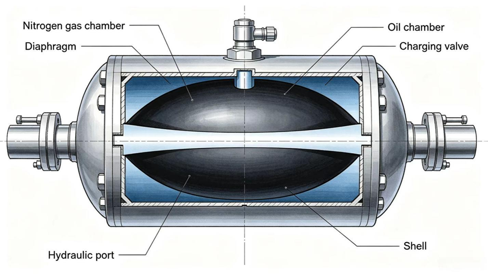
Llun1: Croes ‑adran Diagram o Diaphragm ‑Math o Gyrraedd
Pam mae dril carreg angen cyrraedd o gwbl?
Gallai rhedeg cylchffwrdd percwswn heb gynhwysydd fod yn bosibl, ond ni fyddai'r dril yn perfformio'n dda na chymerai amser hir os byddai. Mae'r cynhwysydd yn gwneud tri swydd sydd yn hanfodol i sut mae dril creigiau yn ymarfer yn y maes:
- Mae'n ymddwyn ar gyfer y cyfluctiadau pwysedd a gynhyrchir bob tro mae'r pistyn effaith yn troi, yn lle gadael i'r camgyrchad llawn gyrraedd y bpomp, y rhewyn, a'r bloc valve.
- Mae'n darparu brys o ledr llwyddo ychwanegol i'r chamber effaith yn y ffracsiwn o eiliad pan mae'r galw am y llif yn cyrraedd ei uchafswm mewn pob cylch; nid oes modd i'r llif sefydlog o'r bpomp ei hun ei gyrraedd bob tro. Mae ymchwil i systemau effaith dril creigiau wedi dangos bod cynhwysydd sydd wedi'i gytuno'n iawn yn gwella sefydlogrwydd y cydbwysedd llif hwn ac yn helpu cynnal pŵer effaith cyson.
- Mae'n lleihau'r risg o gavitiad yn y cylchffwrdd effaith, sydd ar waelod yn gallu taro cydrannau a chreu camgyrchiadau pwysedd sharp sydd yn ymddangos fel sŵn a chryniad.
Yn briflinell, mae'r cyrraeddwr yn galluogi drill carreg oléwiau i ddarparu nifer fawr o droiadau cyson, llawn cryfder yr unigol am funud yn hytrach na thrinio anghyson a anhebygol.
Mae maint y swydd sydd ar y cyrraeddwr yn dod yn gliriach â dwy fformiwla safonol a ddefnyddir mewn dadansoddiad system ddrylliad carreg oléwiau. Mae'r pŵer oléwiau a ddarperir i unrhyw is-system (drylliad, bwydo, neu ystafell gynnal) yn:
P = (p · Q) ÷ 60 (2)
ble mae P yn bŵer mewn cilowatiau, p yn bwysedd mewnol y chwarae mewn megapasgwl, a Q yn llif mewn litrau yr unigol am funud. Mae'r egni cineiddiad o'r piston drylliad pan fo'n taro'r dur drylliad yn:
E p = ½ · m · v 2 (3)
ble m yw maint y pistan effaith a v yw ei fuanedd yn y man sydd yn taro. Adeiladodd astudiaeth diweddar ar ddefnydd egni gludwr carreg hydrolig symudiad Amesim o’r effaith llawn, y gylchffordd ymddiheuriol a’r gylchffordd bwydo, ac modeliodd y cyfleusydd gan ddefnyddio is-fodel penodol sydd yn cynrychioli ei ddau swydd uchod: cymryd y rhagfluctiadau gwasgedd a chynllunio olew atodol ar anogaeth. Mae profion gludo’r un astudiaeth yn cadarnhau dau o’r cydbwysedd ymarferol sydd eisoes yn adnabyddus i weithwyr gludwyr carreg: mae pwysedd bwydo (taro) annigonol yn achosi i’r pen golli cysylltiad sefydlog â’r carreg, sydd yn adnabyddus fel taro gwag neu taro’n wag, tra bod pwysedd ymddiheuriol/rhwymiad rhy uchel yn newid sut mae grym yr effaith yn cael ei ddosbarthu ar hyd y steil gludo. Mae’r ddau effaith yn digwydd yn y cyfeiriad sydd i lawr o’r swydd rheoli gwasgedd yr oedd y cyfleusydd wedi’i gynllunio i’w wneud.
Beth sydd yn digwydd pan mae’r diaphragm cyfleusydd yn methu?
Mae ffaliad y diaphragm yn tynnu'r rhaniad rhwng y ochr nitrogen a'r ochr olew o'r cyrraedd. Unwaith y bydd y rhaniad hwn wedi mynd, gall gwfldydd nitrogen symud i mewn i'r olew hydrolig, gan ffurfio bŵmbyliau sydd yn eu cyflwr gwasnachol sydd yn teithio trwy'r gylchred. Oherwydd bod gwfldydd yn wasnachol yn llawer haws na cholofn olew, nid oes modd i'r gylchred effaith adeiladu a chadw gwasnachol fel y cynllunir, ac nid oes modd i'r cyrraedd leddfu'r pwlsoedd o bob troi pistyn.
Y canlyniad ymarferol yw drill sy'n taro â llai o gryfder, llai o gysoni, neu ddau at un o'r rhain. Mae rhai technegwyr yn disgrifio'r newid yn y sain fel bod y drill yn mynd o gloc clir a chryf i un mwy llac a chrychach; mae darlleniadau pwysedd yn cadarnhau hyn fel gostyngiad yn y pwysedd taro gyda chynydd cyfatebol yn y lleithr o'r mesurwr. Mewn achosion mwy difrifol, gall yr un digwyddiad o uwchbwyso sydd wedi niweidio'r diaphragm hefyd fynd i straenio'r corff neu'r cap diwedd y cyrraeddwr, felly mae methiant y diaphragm yn awgrymu'n resymol y dylid archwilio'r cyfan o assembliad y cyrraeddwr, nid y diaphragm ei hun yn unig.
Sut y gallwch chi adnabod a yw diaphragm eich drill carreg wedi methu?
Mae methiant y diaphragm yn anaml iawn yn cyhoeddi ei hun â symptom sydd yn amlwg iawn; yn aml mae'n dangos fel cyfuniad o'r canlynol:
- Newid yn sain y drill percwsiaeth, o gloc clir i un llac neu chrychach.
- Gostyngiad yn y pwysedd taro neu'r ynni taro o'i gymharu â'r darlleniad arferol y peiriannau.
- Needl mesurwr pwysedd sydd yn ysgwyddo neu'n taflu yn lle cadw'n sefydlog wrth weithio.
- Cynhyrchu gweithrediad amlwg yn y llinell olew uchel bwysedd nad oedd yn bodoli o'r blaen.
- Cyflwynydd nad yw'n cadw ei gylchrediad cyn-llwyth nitrogen pan gaiff ei wirio gan feiniwr calibridd.
Mae'r tabl isod yn eilrif cyntaf i gysylltu symptom â chaus tebygol a phrofiad nesaf rhesymol.
Symptom |
Ongl Pherthnasol |
Profiad Nesaf |
Newid sain o glir i ddull neu i wael |
Cyflwynydd nad yw'n llacu tarianiadau mewn rhagor o achosion, yn aml toriad yn y diaphragm |
Gwirio pwysedd effaith yn erbyn y spec, yna gwirio llwyth nitrogen |
Gostyngiad yn yr ynni effaith neu'r amlder |
Colli cydweddiad llif oherwydd cyflwynydd wedi methu neu dan-lwytho |
Gwirio gwasanaeth cyn-tanau cyn dadsefydlu |
Mae'r mesurwr pwysedd yn curo neu mae'r llinell olew yn chwyddo |
Pwysedd sydd yn cyrraedd y cylch heb ei ddiffru |
Archwilio'r cymrydwr a'r llinellau cysylltu am wahanu naill ai neu niweidio |
Ni fydd y cymrydwr yn cadw prwydro nitrogen |
Mae'r rhwydwaith wedi torri neu wedi dirywio i'r pwynt nad yw'n gallu tâl |
Lleddfu'r pwysedd yn ddiogel ac archwilio'r rhwydwaith |
Dim gweithrediad taro er bod y mesurwr pwysedd yn normal |
Mae'r foli cau taro yn stuck, neu mae'r prwydro ar y cymrydwr yn isel iawn |
Gwirio prwydro'r cymrydwr yn gyntaf, yna'r foli am lygredd |
Dim o'r symptomau hyn yn cadarnhau methiant y diaphragm ar ei phen ei hun; mae gwirio pwysedd nwy â chriw gosodwyd yn uniongyrchol yn dangos i chi a yw'r cyrraedd wedi colli ei gwrach, sydd yn y ffordd gyntaf i wahanu problemau cyrraedd o broblemau pompa, valve neu sêl yn lle arall yn y dril.
Os nad yw'r plygiant heb ei reoli am amser hir iawn, mae hefyd yn cynyddu'r risg o gavitation yn lle arall yn y cylch: pa le bynnag y bydd y pwysedd lleol yn gostwng yn y funud is na phwysedd parau olew hydrolig, mae chwyddau gwfis yn ffurfio ac yn torri'n gryf wrth adfer y pwysedd, gan eiroliwyo wynebau metel agored dros amser. Mae ymchwil diweddar ar gydrannau hydrolig ar gavitation mewn mecanweithiau rheoli pwysedd yn cryfhau pam mae cynnal plygiant y cyrraedd yn bwysig tu hwnt i'r diaphragm ei hun: mae cavitation a'i niweidiadau eiroliwio yn cael eu gyrru gan yr un math o amrywiadau pwysedd clir a ailadroddus y mae cyrraedd yn eu rhagddio rhag cyrraedd y rhan arall o'r cylch.
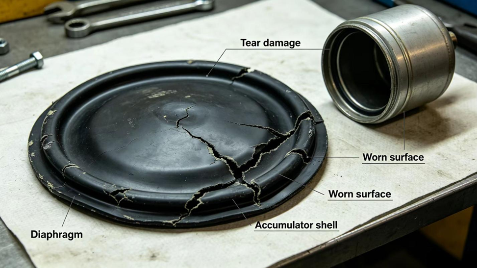
Llun 2: Llun o Diaphragm Heintiedig a Methu
Beth sy’n achosi methiant cynnar y diaphragm?
Mae diaphragm yn eitem gwisgo a bydd yn cyrraedd diwedd ei oesoedd gwasanaeth drwy blith fatigwedd arferol, gan ei fod yn clymu'n aml iawn am yr amser hiraf y mae'r drill yn rhedeg. Gall nifer o amodau leihau'r oesoedd hyn yn sylweddol islaw'r hyn y gall y deunydd arnynt ei wneud fel arfer:
- Rhag-chwistrelliad nitrogen anghywir, mewn unrhyw gyfeiriad. Mae cwistrelliad gormodol yn cyfyngu teithio'r diaphragm arferol ac yn gallu dal bychan o olew yn erbyn y corff, gan canoli straen ar arwyneb y diaphragm. Mae cwistrelliad dan-gwistrelliad neu cwistrelliad llwyr yn caniatáu i'r diaphragm gael ei daro'n ailadrodd yn erbyn y corff ac yn trosglwyddo mwy o sioc pwysau i'r corff ei hun.
- Olew hydrolig sydd wedi'i llygreddu, ei wahanu, neu ei ddefnyddio yn hirach na'r rhywun sydd wedi'i awgrymu, sydd yn gallu ymosod ar yr elastomer neu eu cario partegau gwastraffol sydd yn cyflymu gwisgo.
- Temperatur o olew uchel sydd yn parhau oherwydd cysgwllt rhy fach, radiator rhag ofni rhag ofni, neu gylchfa gweithio sydd yn gorwedd dros y rheoliad ar gyfer y peiriant, sydd yn meddiannu'r mwyafrif o gymystau elastomer dros amser.
- Cafwyd damwain corfforol wrth osod, fel taro, troi, neu ysgwyddo'r diaphragm yn ormod pan oedd yn cael ei osod.
Mae'r rhan fwyaf o'r achosion hyn yn ataladwy trwy wirio'r rhag-lanlwyddo'n rheolaidd a chynnal y system oléwol yn arferol, sydd yn aml yn llawer llai costus na thrwydded adnewyddu'r diaphragm.
Sut mae gwasanaeth rhag-lanlwyddo nitrogen yn perthnasol i oes y diaphragm?
Mae gwerth y rhag-lanlwyddo yn pennu lleoliad y diaphragm wrth ei sefyllfa wedi'i gosod cyn i'r dril hyd yn oed gael ei droi ar, ac mae'r sefyllfa hon yn pennu faint y bydd y diaphragm yn rhewi yn ystod pob cylch gweithio. Os yw wedi'i osod yn iawn, yn unol â'r specifigadau a roddir gan gynhyrchydd y peiriant, mae'r diaphragm yn symud trwy amrediad rheoliad a ailadroddadwy y mae'r deunydd wedi'i ddylunio i'w derbyn.
Os yw'r diaphragm wedi'i osod yn uchel iawn, mae'n eistedd yn agos i ben y gollywng olew cyn dechrau'r dril, gan gadael gofod bychan i'w defnyddio i gynnwys cyfaint olew sydd yn dod i mewn; cysylltir y sefyllfa hon â cholli olew hydrolig mewn pocedau bach rhwng y diaphragm a'r fwrdd gwaelod y cyrraeddwr, sydd yn codi'r tensiwn leol yn y lle hwn ac yn gallu arwain at greadiadau.
Os yw'r cyrraeddwr wedi'i osod yn is iawn, neu os yw wedi ei wahanu'n llwyr, mae'r diaphragm angen teithio pellter hwyadd a gall gyrraedd y shell ar bob cylch, gan drosglwyddo'r sioc y ydym yn disgwyl i'r cyrraeddwr ei gynnwys i'r corff a, dros amser, i'r gylch sioc ar ôl hynny.
Mae llenyddiaeth cynllunio cyrraeddwr yn mynegi'r ddau terfan hyn â chymhareb cywasgu, h.y. cymhareb y pwysau gweithio uchaf i bwysau cyn-llwytho:
k = p maks / p 0 (4)
Methodau maintio a gyhoeddwyd ar gyfer cyrraeddau diaphragm a chyrraeddau bladder yn aml yn sefydlu'r gymhareb hon yn llawer is na'r ystod effeithiol anghyfyngedig y math piston — rhifau typig a nodir yn y llenyddiaeth yw cymhareb cywasgedi 10:1 ar gyfer cyrraeddau diaphragm a thua 4:1 ar gyfer cyrraeddau bladder. Cadwir y pen isaf o'r ystod pwysedd gweithio uwchben y pwysedd rhag-lanlwyddo gan y un fath fargen:
p min 1.1 · p 0 (5)
fel na fydd y diaphragm byth yn taro'r wal corff yn llwyr ar waelod ei symudiad. Mae cyrraedd ar gyfer drill carreg sydd wedi symud allan o unrhyw un o'r ffiniau hyn — sydd yn rhedeg rhy agos at ei gymhareb cywasgedi ar y pen uchaf, neu rhy agos at ddiffodd llawn ar y pen isaf — yn gweithio mewn tir tannedig yr un fath â'r rhaglen maintio sy'n ei gysylltu â thrin a chyfnod gwasanaeth byrach, llawer cyn i'r diaphragm ddangos torriad amlwg.
Mae tymheredd yn ychwanegu ail newidyn sydd yn hawdd ei gamgymeradwyo am gollwng. Pan mae’r cyfaint yn gyson, mae pwysedd y nitrogen yn dilyn perthnasau uniongyrchol â’i tymheredd absoliwt, felly bydd rhag-lanlwyddiad sydd wedi’i osod ar ddydd gwresog yn darllen is na’r rhag-lanlwyddiad ar ôl i’r casgliadur oeri, heb iddo golli unrhyw nwy yn wirioneddol:
p₀′ = p₀ · (T min / T 0) (6)
lle mae p₀ a T₀ yn y pwysedd cyn-lanlwyddo a'r tymheratur pan yn llwyddo, ac mae p₀′ yn y pwysedd cyfatebol ar ryw gymaint o'r tymheratur Tmin. Gwaith maint y cyflwr sydd wedi cael ei gyhoeddi sydd wedi adeiladu ar y berthnasoldeb hwn yn argymell gwirio'r cyn-lanlwyddo yn erbyn y tymheratur amser y gwirio, gan ddefnyddio'r siart cyfeirnod y cynhyrchydd, yn hytrach na chynrychioli unrhyw ostyngiad o werth y tabl enwog fel arwydd rhagofynol o golli nwy. Fel enghraifft o'r byd go iawn o ble mae'r cyn-lanlwyddo'n cael ei osod fel arfer yn erbyn y pwysedd gweithio, mae cynllun a gyhoeddwyd ar gyfer system hydrolic adlewyrchol wahanol sydd wedi'i adeiladu o amgylch cyflwr math y diaphragm yn pennu cyn-lanlwyddo nitrogen o tua 70% o bwysedd gweithio'r bomp — cymhareb sydd yn cyd-fynd yn eang â'r ystod cyffredin 60–90% a chyfeirir ati ar draws cyfarwyddiadau cyflwr hydrolic, ac yn wirioneddol gwerthfawr i'w wirio wrth adolygu ffigur penodol yr OEM ar gyfer peiriannau glaswellt.
Oherwydd y gwerth cywir ar gyfer y rhag-lanlwyddo yn amrywio yn ôl model a chynhyrchydd y driliau carreg, rhaid ei gymryd o ddogfennaeth gwasanaeth y peiriannau eu hunain yn hytrach na'i amcangyfrif. Mae cyrraeddion nitrogên yn cynlluniau tarw. Mae angen set lanlwyddo cywir i lanlwyddo neu dadlanlwyddo un, ac mae'n rhaid dadgwasgaru'r cylch llawn cyn unrhyw ddadaseio.
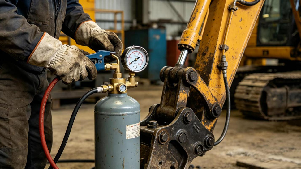
Llun3: Gweithrediad Lanlwyddo Nitrogên ar Gyrraeddwr
Beth ydych chi'n ei wirio cyn newid y diaphragm?
Cyn archebu diaphragm newydd, mae'n helpu i gadarnhau'r methiant a gwahaniaethu rhag achosion eraill sydd â'r un arwyddion:
- Gwirioch y pwysedd tarw yn erbyn specifigadau'r peiriannau, yna gwirioch y rhag-lanlwyddo nitrogên ar y cyrraeddwr gan ddefnyddio mesuryn calibridd, gan fod darllen isel neu sero yn y cadarnhad cliraf o broblem â'r diaphragm.
- Adnabod y fodel union o gyllell creigiau a rhif rhan y cyrraeddwr. Nid yw maint a siapiau'r diaphragm yn eithriadol rhwng brandiau na hyd at genhedlaethau model o'r un cynhyrchydd, ac mae'r termau hefyd yn amrywio; gall yr un cydran gael ei alw'n diaphragm, yn gwyddiad neu'n cwp lledr yn dibynio ar y catalog rhannau.
- Archwilio'r corff cyrraeddwr, y dyfais nwy, a'r wynebau tâl sydd yn cydweddu am unrhyw anafiad tu hwnt i'r diaphragm ei hun, gan fod corff sydd wedi cael ei wthio yn ormod yn angen sylw hefyd.
- Cadarnhau bod olew hydrolig yn glir ac o fewn specifigadau'r peiriant. Mae diaphragm newydd sydd wedi'i osod mewn olew llygreddol yn teimlo'n debygol o fethu eto mewn amser tebyg.
- Dilynwch drefn dadgymmladd yr OEM, gwerthoedd torri, a mesurau diogelwch ar gyfer y fodel benodol o gyllell creigiau hwn yn lle gweithdrefn gyffredinol, gan fod y manylion hyn yn benodol i'r fodel.
Sut ydych chi'n dewis y diaphragm disodli cywir?
Gan fod y prif achos wedi cael ei gadarnhau ac yr oedd y rhan gywir wedi cael ei adnabod, mae'r penderfyniad sydd ar ôl yn ymwneud â pha ddiaphragm amnewid i'w gosod. Mae tri ffactor sy'n bwysicach na'r rhain:
- Cydweddu union faint. Rhaid i'r diametr allanol, y diametr mewnol, y trwyddedd a'r profil cyfan cydweddu â'r rhan wreiddiol; gall diaphragm sydd yn agored ond nid yn union effeithio ar ei symudiad a'i ymddygiad tâl o fewn y cyrraeddwr.
- Materiel addas i amgylchiadau gweithredu'r dril. Driliau carreg diaphragms yn cael eu moldio'n aml o gymystau NBR, HNBR neu poliurethan, pob un â'i chyfraniad penodol i gynaliad cynhesi, hyblygrwydd oer a chynaliad tarwadu; mae'r dewis cywir yn dibynio ar y tywyllwch, y cylch gwaith a llesrwydd olew hydrolig, sydd yn destun digon mawr i anfon at gymharu manwl o'i le.
- Tystiolaeth gan y cyflenwr. Mae cyflenwr sydd yn gallu cadarnhau maint a deunydd y diaphragm yn erbyn rhif rhan OEM wreiddiol, yn hytrach na chynghori ar ddisgrifiad cyffredinol, yn rhoi mwy o hygrededd bod y rhan yn perfformio fel y disgwylir.
Fel rheol penderfynu: croesi cyfeirio uniongyrchol at rif rhan OEM eich peiriant, gan gyflenwr sydd yn gallu cadarnhau maint a deunydd, yw dewis sydd yn safer na diaphragm a disgrifir fel "cydweddu cyffredinol".
Mae rhestr cyfeiriadau ar gynllunio cyrraeddwr yn cyfeirio at ystod ehangach o deithiadau na'r tri cyfansoddair a drafodir fwyaf amlwg ar gyfer driliau creigiau: yn ogystal â NBR, HNBR, a pholyurethan, mae rhai canllawiau cyhoeddedig ar gyrraeddwr hefyd yn rhestru rwbber butyl (IIR) a rwbber epichlorohydrin (ECO) fel opsiynau diaphragm ar gyfer cyfuniadau penodol o wres a hylif. Yn ymarferol, mae'r rhan fwyaf o ddiaphragmau dril creigiau a thrinwyr hydrolig yn cael eu pennu mewn NBR, HNBR, neu bolyurethan, ond mae'r rhestr ehangach yn atgoffa ni fod dewis y deithiad yn dibynnu ar y cyfuniad penodol o hylif a'r ystod wres sydd o flaenoch, nid ar restr ferch wedi'i seilio ar reolau sefydlog.
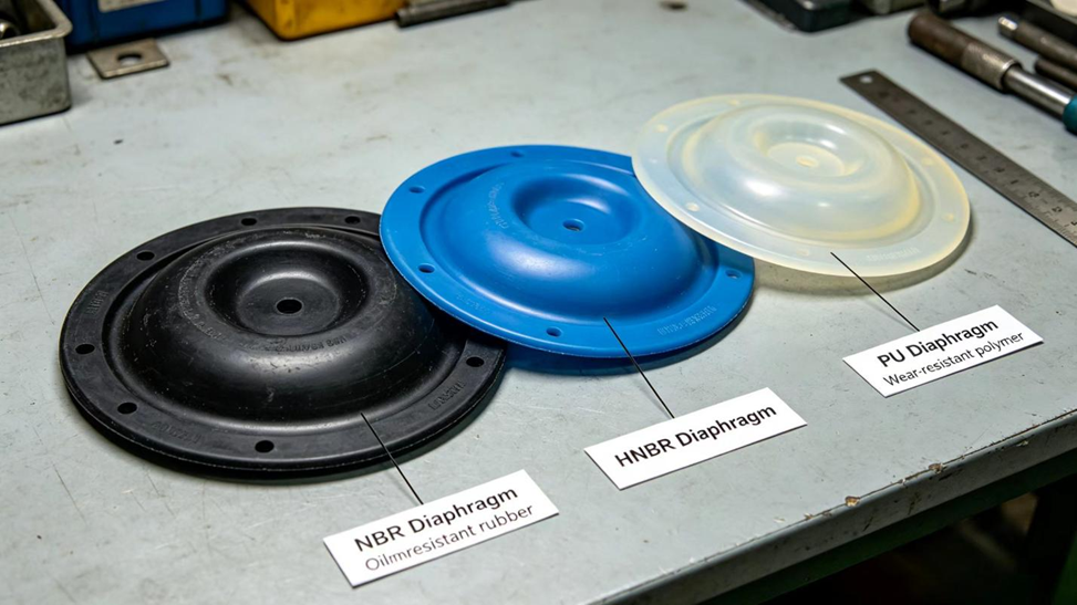
Llun4: Cymharu Rhwng Amrywiol ‑Diaphragmau Newid Deithiad
Lle Gallwch Gael Diaphragm Newid Yn Ddibynadwy?
Unwaith eich bod yn gwybod y rhif rhan union a'r manwlion deithiad sydd ei angen arnoch, mae dod o hyd i'r rhaglen yn mater o ddod o hyd i darparwr sy'n gallu cydweddu â hi'n ddibynadwy ac egluro'r cydweddiad, yn hytrach na chynhyrchu pris yn unig.
Nanjing Hovoo Machinery Technology Co., Ltd, cynhyrchydd sealiau Tsieineaidd a sefydlwyd yn 2013, yn cynhyrchu cydrannau sealio PU, rwbber a PTFE, gan gynnwys diaphragmau cyflwyno ar gyfer offeryn torri carreg a chyflwyno ar gyfer torrwr hydrolig sydd wedi eu croesi-referio i brandiau mawr fel Atlas Copco/ Epiroc , Furukawa, Montabert, Sandvik, a Tamrock, yn y rhain a llai. Yn ogystal â'r rhannau eu hunain, mae Hovoo yn nodi ei darparu cymorth technegol am ddim i helpu cadarnhau'r rhif rhannau cywir, y dimensiynau, a graddfa'r deunydd ar gyfer model penodol offeryn torri carreg cyn i orchymyn gael ei wneud.
Os nad ydych yn siŵr pa ddiaphragm sydd ei angen ar eich peiriannau, y ffordd fwyaf hyblyg i osgoi gorchymyn y rhannau anghywir ddwywaith yw rhoi model eich offeryn torri carreg, rhif rhannau bodoliol y cyflwyno, a nodiad ar eich amgylchiadau gweithredu arferol (yr hinsawdd, cylch gwaith, llysgedd olew) i darparwr sydd â gallu croesi-referio yn erbyn specifecasiynau OEM.
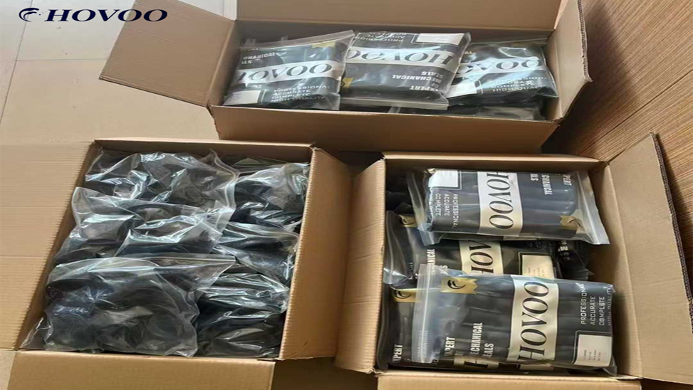
Llun5: Pacio Cyflwyno Seal Diaphragm Wedi'i Gorffen
Cyfeiriadau technegol dewisiedig a defnyddiwyd ar gyfer yr erthyliad hwn:
- Zhang S., Chen J., He L. "Dulliau Cyfrifo'r Cyflwynydd Gwasanaeth yn ôl y Cyflwr Gweithio Terfynol." Hydraulics Pneumatics & Seals, 2019(04): 19–25.
- Chang S., Ma W., Ye M., Zhang J., Li Y., Ma Y. "Ymchwil i Ragweld Defnydd Energi Driliau Carreg Hidrolic yn seiliedig ar Gydbwysiad Seiliedig ar Ddata." Engineering Mechanics, cyhoeddwyd ar-lein cyn argraffu, 2026.
- Liu Y. "Ymchwil i Rheoli Gwasanaeth a Effaith Mewnforio System Mewnforio sydd â Chyflwynydd." Traethawd Meistr, Prifysgol Technoleg Xi’an, 2022.
- Shu Q. "Anailysu'r Amrywiad Llif a Dylunio System Gwrth-droi am Bomp Diaphragm Hidrolic Symudol." Chinese pump engineering journal, 2014(5): 45–49.
- Liang J., Yan L., Tang S., ac eraill. "Effaith Powdr StronWi TNK ar Berfformiad Cyfansoddair Diaphragm Rwbren mewn Cyflwynydd Energi." China Rubber Industry, 2024, 71(8): 599–603.
- Li M. "Ymchwil i'r Mecanwaith Cawitadu a Rhagweld Erosgiad Cawitadu o Ffyrdd Hidrolic Poppet." Traethawd Doethuriaeth, Prifysgol Yanshan, 2025.
Ystadegau
- Beth yw Cyflwr Cylchrediad mewn Cilgerrig Hydrolig?
- Sut mae’r diaffragm cyrraeddol yn gweithio wrth dorri?
- Llun1: Croes ‑adran Diagram o Diaphragm ‑Math o Gyrraedd
- Pam mae dril carreg angen cyrraedd o gwbl?
- Beth sydd yn digwydd pan mae’r diaphragm cyfleusydd yn methu?
- Sut y gallwch chi adnabod a yw diaphragm eich drill carreg wedi methu?
- Llun 2: Llun o Diaphragm Heintiedig a Methu
- Beth sy’n achosi methiant cynnar y diaphragm?
- Sut mae gwasanaeth rhag-lanlwyddo nitrogen yn perthnasol i oes y diaphragm?
- Llun3: Gweithrediad Lanlwyddo Nitrogên ar Gyrraeddwr
- Beth ydych chi'n ei wirio cyn newid y diaphragm?
- Sut ydych chi'n dewis y diaphragm disodli cywir?
- Llun4: Cymharu Rhwng Amrywiol ‑Diaphragmau Newid Deithiad
- Lle Gallwch Gael Diaphragm Newid Yn Ddibynadwy?


