

 EN
 AR
 CS
 DA
 NL
 FI
 FR
 DE
 EL
 IT
 JA
 KO
 NO
 PL
 PT
 RO
 RU
 ES
 SV
 TL
 IW
 ID
 LV
 SR
 SK
 VI
 HU
 MT
 TH
 TR
 FA
 MS
 GA
 CY
 IS
 KA
 UR
 LA
 TA
 MY

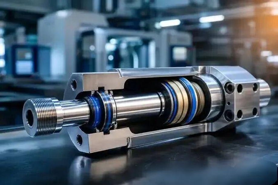
Someone once asked: can an FKM or FFKM O-ring that has sat in a warehouse for eight years still be used? The answer is usually yes. Yet the same batch, fitted to a 130°C gearbox, can harden and start weeping oil within eight months.
Seal life is not a rated value. It is the result of six variables working together: material, temperature, pressure, media, installation and storage. This article gives figures wherever figures exist and tables wherever a table will do, so you can keep it as a handbook.
Material sets the ceiling, temperature sets the pace, pressure and clearance decide survival, media are the wild card, and installation and storage set the floor.
1. Material: See the Ceiling First
On the question of life, the first step is not to ask “how long can it last?” but “how long can this rubber itself last?” The industry uses two sets of rules, and many people know only one of them.
ISO 2230 divides elastomers into Groups A, B and C, and gives an “initial storage period plus an extension period after passing inspection”:
Table 1 ISO 2230 Storage Life Groups for Rubber
Group |
Typical elastomers |
Initial period |
Extension |
Group A |
NR, SBR, BR, polyurethane |
5 years |
2 years |
Group B |
NBR, HNBR, CR, ACM, IIR |
7 years |
3 years |
Group C |
EPDM, FKM, FFKM, silicone |
10 years |
5 years |
SAE AS5316 (formerly ARP5316) is far more lenient. Many elastomers are simply marked “unlimited,” based on stock parts tested over more than thirty years. Here is a side-by-side comparison:
Table 2 Storage Life of 13 Materials under the Two Standards
Material |
ISO 2230 |
AS5316 |
NBR (nitrile) |
7 years +3 |
15 years |
HNBR (hydrogenated nitrile) |
7 years +3 |
15 years |
CR (chloroprene) |
7 years +3 |
15 years |
ACM (acrylate) |
7 years +3 |
15 years |
IIR (butyl) |
7 years +3 |
Unlimited |
EPDM (ethylene propylene) |
10 years +5 |
Unlimited |
FKM (fluoroelastomer) |
10 years +5 |
Unlimited |
FFKM (perfluoroelastomer) |
10 years +5 |
Unlimited |
VMQ (silicone) |
10 years +5 |
Unlimited |
FVMQ (fluorosilicone) |
10 years +5 |
Unlimited |
AFLAS (FEPM) |
10 years +5 |
Unlimited |
AU/EU (polyurethane) |
5 years +2 |
5 years |
SBR (styrene-butadiene) |
5 years +2 |
3 years |
PTFE |
Aging not controlled |
Unlimited |
The two standards do not contradict each other; they simply price risk differently. ISO is the more conservative one, followed by the European system and many OEMs. AS5316 is closer to measured data and is common in the North American aerospace chain. Follow whichever one your drawing or contract names, and do not pick the one you like better. Both count from the cure date: the “2Q24” on the package means the part was molded in the second quarter of 2024.
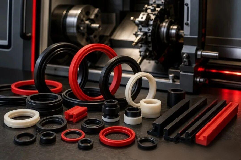
2. Material Data at a Glance: Temperature, Hardness, Resistance, Permeability
This section is all numbers, so it is worth saving as an image. Start with temperature and hardness. Note that the “continuous limit” is not the “short-term peak”; a gap of 20–40°C between the two is common.
Table 3 Temperature Range and Hardness of 13 Sealing Materials
Material |
Low-temp limit |
Continuous upper limit |
Hardness (Shore A) |
NBR (nitrile) |
-40℃ |
+120℃ |
40~90 |
HNBR (hydrogenated nitrile) |
-30℃ |
+150℃ |
50~90 |
ACM (acrylate) |
-30℃ |
+150~180℃ |
55~85 |
CR (chloroprene) |
-40℃ |
+120℃ |
50~90 |
IIR (butyl) |
-40℃ |
+120℃ |
50~80 |
EPDM (ethylene propylene) |
-50℃ |
+150℃ |
40~90 |
FKM (fluoroelastomer) |
-20℃ |
+200~230℃ |
50~90 |
FFKM (perfluoroelastomer) |
-15℃ |
+260~300℃ |
60~90 |
VMQ (silicone) |
-60℃ |
+200~250℃ |
30~80 |
FVMQ (fluorosilicone) |
-55℃ |
+200℃ |
40~80 |
AFLAS (FEPM) |
-10℃ |
+200℃ |
70~90 |
AU/EU (polyurethane) |
-30℃ |
+80℃ |
70~95 |
PTFE |
-200℃ |
+260℃ |
55~65 D |
Note: PTFE has no elastomer hardness; its figure is Shore D. Polyurethane has high hardness but the poorest temperature resistance, and it is the grade most often chosen wrongly.
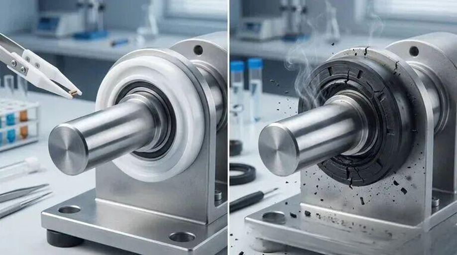
Temperature solves only half of the problem; the other half is the medium. The table below gives a rough screen in four grades (Excellent / Good / Fair / Poor). The final decision still needs an immersion test.
Table 4 Quick Reference: Media Resistance by Material (Rough Screening)
Material |
Mineral oil |
Fuel / solvents |
Hot water / steam |
Ozone / weathering |
NBR |
Excellent |
Good |
Fair |
Poor |
HNBR |
Excellent |
Good |
Good |
Good |
ACM |
Excellent |
Poor |
Poor |
Good |
CR |
Good |
Fair |
Fair |
Good |
IIR |
Fair |
Poor |
Good |
Excellent |
EPDM |
Poor |
Poor |
Excellent |
Excellent |
FKM |
Excellent |
Excellent |
Poor |
Excellent |
FFKM |
Excellent |
Excellent |
Good |
Excellent |
VMQ |
Fair |
Poor |
Good |
Excellent |
AFLAS |
Good |
Fair |
Excellent |
Excellent |
AU/EU |
Excellent |
Fair |
Poor |
Good |
PTFE |
Excellent |
Excellent |
Excellent |
Excellent |
Note: FKM loses out in hot water and steam, and EPDM loses out in mineral oil. These are the two most common selection failures in the field.
Two more parameters are easy to overlook: gas permeability and cost. In vacuum, gas-charged accumulators and refrigeration, permeability matters more than temperature resistance.
Table 5 Gas Permeability and Relative Cost (NBR = 1 as baseline)
Material |
Gas permeability |
Relative unit price |
IIR (butyl) |
0.1 |
2~3× |
FKM (fluoroelastomer) |
0.1~0.3 |
8~15× |
FFKM (perfluoroelastomer) |
0.1~0.2 |
50~100× |
HNBR |
0.3~0.5 |
3~5× |
NBR (nitrile) |
1 (baseline) |
1× |
AU/EU (polyurethane) |
0.5~1 |
1.5~2.5× |
EPDM |
1.5~3 |
1.2~2× |
VMQ (silicone) |
10~30 |
3~6× |
PTFE |
5~15 |
5~10× |
This table explains two things: why vacuum systems prefer FFKM, FKM or butyl over cheap silicone, and why “expensive” never means “correct.” Silicone tolerates higher temperatures than NBR, but its gas permeability is more than ten times higher.
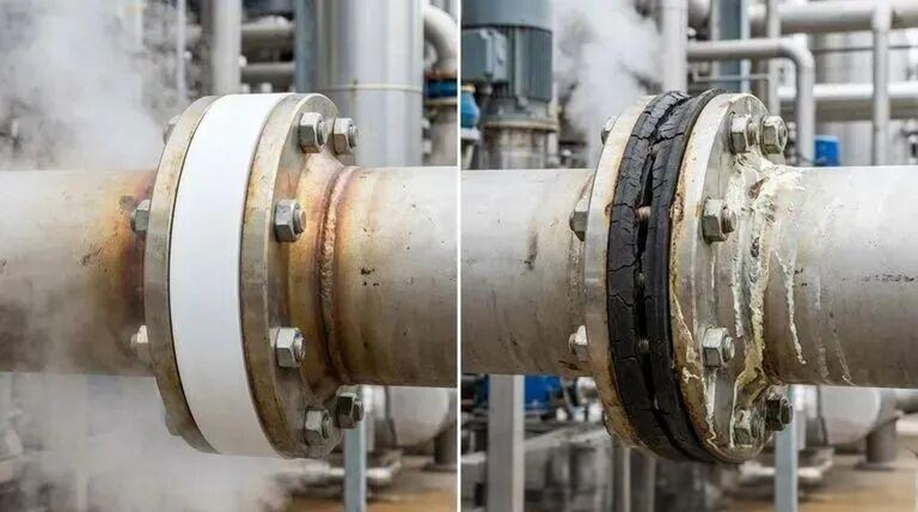
3. Temperature: The Only Variable That Runs on an Exponent
By the Arrhenius rule, every 10°C rise roughly doubles the aging rate, and 2 to 3 times is common in measurements. What does doubling mean? See this table:
Table 6 Life Conversion per 10°C Rise (100°C as baseline)
Service temperature |
Aging rate |
Relative life |
100℃ |
1× |
100% |
110℃ |
2× |
50% |
120℃ |
4× |
25% |
130℃ |
8× |
12.5% |
140℃ |
16× |
about 6% |
Note that each step is a multiplication, not a subtraction. A seal that lasts 4 years at 100°C has only half a year left at 130°C. That is not one year less; it is only one-eighth of the life.
How temperature actually translates into life is judged industry-wide by compression set (ASTM D395 Method B: compress 25%, 70 hours, measure recovery):
Table 7 Compression Set (70 h; lower is better)
Material |
100℃ |
150℃ |
200℃ |
225℃ |
NBR 70 |
25~40% |
50~70% |
— |
— |
HNBR 70 |
15~25% |
35~50% |
60~80% |
— |
FKM 75 |
10~18% |
18~30% |
30~45% |
45~60% |
VMQ 70 |
15~25% |
25~40% |
40~55% |
55~70% |
AFLAS 75 |
15~25% |
25~40% |
35~50% |
50~65% |
FFKM 75 |
8~15% |
12~20% |
18~30% |
25~40% |
This table is more honest than any marketing line. 40% is a hard threshold: once compression set passes 40%, an O-ring has essentially lost its rebound, and low-pressure applications begin to leak. The “—” in the NBR 150°C column does not mean there is no data; it means life should no longer be discussed at that temperature. Likewise, FKM at 225°C still has data, but it already runs at 45–60%, so whether it can be used is another question.
There is one more mistake that is very easy to make: using “oil temperature” as “seal temperature.” A rotary shaft seal lip works on an oil film only microns thick, and all the frictional heat builds up in a ring-shaped band less than 0.5 mm wide at the lip. Measured lip temperature is 10–40°C above oil temperature, about 20°C more again for seals with a dust lip, and the gap grows with speed and pressure. In a system with 90°C oil, the lip may already be enduring 120°C, and life must be calculated at 120°C, not 90°C.
Low temperature is a cost too. At -50 to -60°C, a rubber that is not low-temperature grade has almost no initial stress left; even a low-temperature compound has less than 25% of its room-temperature initial stress. A leak at that point does not mean the seal is broken, only that it has temporarily lost its elasticity. Leaking on a cold start and stopping once warm is the classic sign, so do not rush to replace the part.
Condition → Action: if the design temperature is less than 20°C below the material’s continuous limit, either move up one material grade, or switch to synthetic oil or high-temperature grease, add cooling, or lower the speed. Do not expect to tough it out by raising the compression ratio; that only overdraws the elasticity in advance.
4. Pressure and Clearance: Mostly Extruded, Not Crushed
Here is a counter-intuitive conclusion: with a sound design, pressure alone does not crush an O-ring. The main cause of high-pressure failure is extrusion into the clearance. Pressure pushes the rubber into the gap between mating surfaces, and during reciprocating motion a piece gets sheared off, which the trade calls nibbling. Trouble comes when three conditions line up: high pressure, large clearance and low hardness. 150 bar is the practical dividing line. Beyond it, either raise the hardness to 80–90 Shore A or add a PTFE back-up ring.
The limits for shaft seals are even narrower, because they are meant only for zero or very low pressure. This set of numbers is worth posting at the workstation:
Table 8 Quick Reference: Operating Limits for Rotary Shaft Seals
Parameter |
Normal limit |
Consequence when exceeded |
Shaft surface Ra |
0.2~0.8 μm |
Too rough wears the lip; too smooth cannot hold an oil film |
Shaft hardness |
≥30 HRC |
Grooving and scoring (dirty media or high speed needs ≥55) |
Eccentricity / runout |
≤0.25 mm TIR |
One-sided wear; life is cut in half |
Surface speed |
<15 m/s |
Lip temperature jumps and aging accelerates |
Working pressure |
0.02~0.05 MPa |
Lip is pushed off the shaft; use a pressure-type seal |
Lip temperature |
Oil temperature +10–40°C |
Calculating life from oil temperature is a miscalculation |
Compression ratio and groove depth are the other half of an O-ring’s foundation. Squeeze too hard and stress relaxation is fast; too little and it leaks at low pressure:
Table 9 Rules of Thumb for O-ring Compression and Groove Depth
Seal type |
Compression |
Groove depth (rule of thumb) |
Recommended hardness |
Static (face) |
15~25% |
Cross-section × 0.70 |
70~80 |
Static (radial) |
15~20% |
Cross-section × 0.72 |
70~80 |
Reciprocating dynamic |
10~15% |
Cross-section × 0.60 |
80~90 |
Rotary dynamic |
8~12% |
Cross-section × 0.58 |
85~90 |
Note: the inner diameter is pre-stretched to shaft diameter × 0.98, and groove width leaves expansion allowance at cross-section × 1.15. Use these three factors together; do not pick just one.
Another point often overlooked: pressure pulses hurt more than constant high pressure. Constant pressure is a static load, while pulses cause fatigue. After several hundred thousand cycles, the rubber’s rebound is worn away bit by bit, and in the end the seal does not burst but slowly seeps.
5. Media: It Is Not Whether It Resists, but How Long and How Hot
Writing “oil resistant” on a selection chart is really a meaningless statement. The real questions are: which oil, what temperature, how long the immersion, and how much swelling is allowed. Volume swell per ASTM D471 is the most direct yardstick:
Table 10 Volume Swell (ASTM D471, 70 h)
Medium |
NBR |
HNBR |
FKM |
FFKM |
IRM 903 oil, 100°C |
+15~30% |
+5~15% |
+3~8% |
+3~6% |
Fuel C, 23°C |
+30~60% |
+15~30% |
+5~15% |
+3~8% |
Methanol M85, 23°C |
+25~35% |
+18~25% |
+10~20% |
+3~8% |
Water, 100°C |
-3~+5% |
-3~+5% |
0~+3% |
0~+3% |
Note: EPDM often swells by more than 60% in mineral oil, up to disintegration, so it is not included in the comparison.
The difference is not whether it can be used but whether the groove can still hold it. Once volume rises by more than 15%, the groove fill ratio changes, the O-ring is crushed by itself, and a dynamic seal will also grip the shaft.
Sneakier than swelling is secondary reaction. When NBR soaks in biodiesel, it looks at first like simple swelling, a purely physical effect. But fatty acid methyl esters keep attacking the nitrile groups, crosslink density rises, and the end result is “swollen and hard.” This failure is invisible in the early stage, and by the time it is noticed the seal has hardened and cracked. Lubricating oil is not neutral either: at high temperature it oxidizes and its additives break down, and the products attack the seal material in turn. When you change oil brand or additive system, it is best to confirm compatibility again at the same time.
Condition → Action: for a new medium or a changed oil, check Tables 4 and 10 first, then run a 70 h immersion test (volume change, hardness change and tensile strength retention). Install only when all three are in hand.
6. Installation and Storage: Half of Early Failures Happen Before the Seal Goes On
Installation first, because it accounts for the most causes. Scratched lips, O-rings twisted like rope and dry assembly without lubricant make up well over half of early field failures. The first two are technique and the third is common sense: a few minutes of dry rubber friction can burn a hardened ring around the lip.
Then storage, which is the area most often overlooked across a whole plant. The storage conditions in the two standards are not very different, and both hinge on one point: no stress.
Table 11 Storage Conditions under the Two Standards
Item |
ISO 2230 |
AS5316 |
Temperature |
<25°C (preferably <15°C) |
15~38℃ |
Relative humidity |
<70% (PU <65%) |
<75% (PU <65%) |
Light |
Avoid direct sun and strong UV |
Same as left |
Ozone sources |
Keep away from motors, welders and high voltage |
Same as left |
Stress |
No stretching, compression or hanging |
Same as left |
Packaging |
Opaque PE ≥75 μm |
Individual or sealed bulk packaging |
Remember the five enemies: heat, ultraviolet light, ozone, deformation under stress, and contact materials. The contact material most often missed is the PVC bag. Plasticizer migrates into the rubber and scraps a good batch outright; copper, manganese and solvents do the same.
Condition → Action: expired stock. Do not scrap it outright, and do not use it outright. Sample a representative part and check appearance (look for cracks at 10× magnification), hardness and compression set. Extend only if all three pass. For critical duty such as pressure vessels and downhole service, expired parts are not used by default.
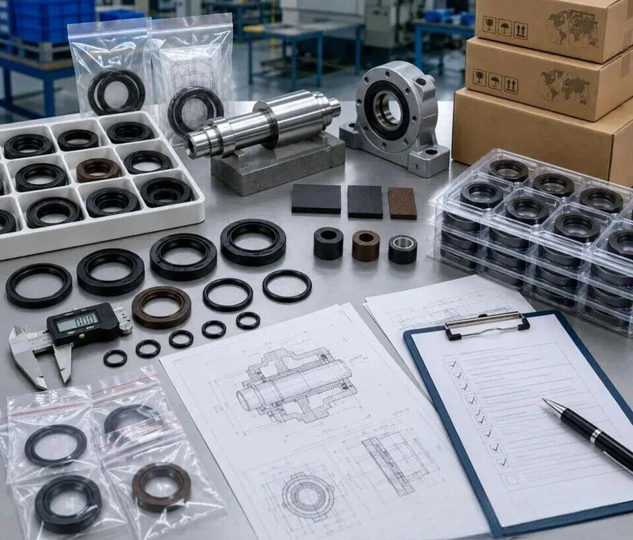
Ten Quick Rules, Worth Copying Down
1. First confirm whether you are calculating by ISO 2230 or AS5316; the two sets of figures are not interchangeable.
2. Check compression set at the target temperature; 40% is the red line.
3. Calculate lip temperature, not oil temperature: oil temperature +10–40°C, and another +20°C with a dust lip.
4. Estimate life as halving for every 10°C rise, then add a safety factor.
5. Above 150 bar, check the clearance, hardness and back-up ring together.
6. For a new medium, run a 70 h immersion test and measure volume, hardness and strength.
7. For vacuum or accumulators, look at gas permeability first, not just temperature resistance.
8. Shaft eccentricity ≤0.25 mm TIR, Ra 0.2–0.8 μm, and always lubricate during assembly.
9. Store below 25°C, away from light and ozone, lying flat and unstressed, and count shelf life from the cure date.
10. Decide the fate of expired parts by test data, not by feel.
The seal itself is not expensive; downtime is. What truly decides life is often not the material code on the purchase order, but whether the lip temperature was calculated at design, whether that coat of oil was applied at assembly, and whether the warehouse kept the part away from the radiator.
What is the real temperature at the sealing point of the equipment in front of you? Check the records. The answer to most “short life” cases is hidden in that number.
This article is worth bookmarking, to pull out and check against when selecting or replacing seals. You are also welcome to leave a “temperature” in the comments with your operating temperature, medium and current material, and I will help you see how much margin the selection still has.
Table of Contents
- 1. Material: See the Ceiling First
- 2. Material Data at a Glance: Temperature, Hardness, Resistance, Permeability
- 3. Temperature: The Only Variable That Runs on an Exponent
- 4. Pressure and Clearance: Mostly Extruded, Not Crushed
- 5. Media: It Is Not Whether It Resists, but How Long and How Hot
- 6. Installation and Storage: Half of Early Failures Happen Before the Seal Goes On
- Ten Quick Rules, Worth Copying Down


