

 EN
EN
 AR
AR CS
CS DA
DA NL
NL FI
FI FR
FR DE
DE EL
EL IT
IT JA
JA KO
KO NO
NO PL
PL PT
PT RO
RO RU
RU ES
ES SV
SV TL
TL IW
IW ID
ID LV
LV SR
SR SK
SK VI
VI HU
HU MT
MT TH
TH TR
TR FA
FA MS
MS GA
GA CY
CY IS
IS KA
KA UR
UR LA
LA TA
TA MY
MY
Il problema della diagnosi di 'battuta debole'
Gli operatori descrivono un impatto debole in modo pressoché identico, indipendentemente dalla causa effettiva: «il martello demolitore non colpisce più con la stessa forza di una volta». Questa descrizione comprende cinque modalità di guasto distinte, ciascuna richiedente una soluzione diversa. Applicare la soluzione errata comporta spreco di tempo e denaro. Sostituire, ad esempio, le guarnizioni quando il vero problema è una bassa pressione di azoto richiede diverse ore di lavoro senza apportare alcun miglioramento all’energia d’urto. Il kit di guarnizioni era perfettamente funzionante; l’azoto no.
La perdita di energia d'impatto avviene attraverso due ampie vie. La prima è rappresentata dall'energia che è stata generata correttamente, ma che non ha raggiunto la zona di frattura — ad esempio, un funzionamento eccentrico dell'utensile, boccole usurate, carichi laterali o qualsiasi altro fattore che devia l'energia del pistone dalla direzione assiale dell'impatto. La seconda via riguarda l'energia che non è mai stata generata al livello massimo — ad esempio, pressione di azoto insufficiente, portata d'olio inadeguata, regolazione errata della valvola di sicurezza o olio contaminato che degrada il circuito idraulico. Entrambe le vie producono lo stesso sintomo percepibile dall'operatore sul comando: la roccia non si frattura. Per distinguere quale delle due vie sia responsabile, è sufficiente effettuare una singola misurazione per ciascuna, senza dover procedere a uno smontaggio completo.
Esiste inoltre una terza categoria che la maggior parte delle guide per la risoluzione dei problemi omette: sovraccarica di azoto. Se la pressione di azoto nella testa posteriore supera il valore specificato, il pistone non riesce a compiere tutta la sua corsa verso l’alto prima che la pressione del gas lo contrasti. L’attrezzo scatta con una corsa ridotta, erogando quindi un’energia minore ad ogni colpo rispetto a un’unità correttamente caricata. Un’elevata pressione di azoto può risultare identica, dal punto di vista dell’operatore, a una pressione bassa di azoto. In un caso si ottiene un ritorno lento e debole del pistone; nell’altro si ha una corsa verso il basso debole e breve. Il manometro indica quale dei due casi si verifica.
Cinque cause — Sintomo, Primo controllo, Soluzione
La tabella analizza le cinque cause più comuni in ordine di facilità di diagnosi: si inizia con i controlli che richiedono due minuti, per passare successivamente a quelli che richiedono lo smontaggio.
|
Sintomo |
Causa probabile |
Primo controllo |
- Sistemi |
|
Colpo debole, difficoltà nel lavorare materiali precedentemente gestiti senza problemi |
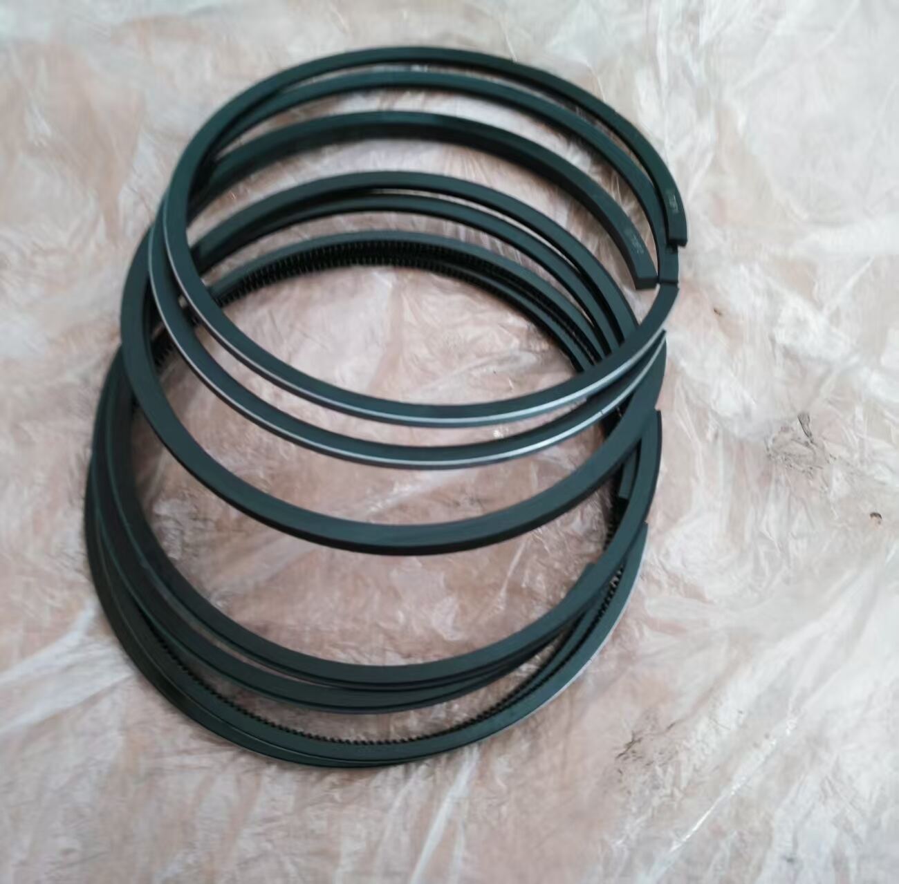
Pressione di azoto troppo bassa |
Collegare il kit di ricarica; confrontare la lettura con il valore specificato (tipicamente 55–60 bar per unità di media grandezza) |
Ricaricare con azoto secco fino alla pressione specificata; se la pressione scende nuovamente entro una settimana, la membrana è danneggiata — sostituire l’accumulatore |
|
BPM bassi, temperatura dell’olio che aumenta rapidamente |
Portata insufficiente dal carrello o linea di ritorno ostruita |
Misurare la portata effettiva all’ingresso del frantumatore sotto carico — non fare riferimento al valore indicato sulla scheda tecnica della macchina |
Eliminare l’ostruzione sulla linea di ritorno; verificare che la valvola di sicurezza sia regolata a 15–20 bar sopra la pressione di esercizio del frantumatore, e non alla stessa pressione |
|
L’energia di frantumazione è diminuita gradualmente nel corso di alcune settimane |
Usura della bussola — lo strumento ruota decentrato, dissipando energia lateralmente |
Rimuovere lo scalpello; misurare il gioco tra il gambo dello scalpello e l’alloggiamento interno della bussola; un valore superiore a 0,5 mm nella maggior parte dei modelli indica la necessità di sostituzione |
Sostituire la bussola interna; ispezionare il gambo dello scalpello per individuare un’usura asimmetrica che confermi il funzionamento decentrato |
|
Perdita improvvisa di potenza dopo l’impatto con un masso di dimensioni eccessive o con una superficie particolarmente dura |
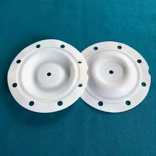
Danno da sparo a vuoto — il pistone ha colpito senza resistenza, comprimendo l'ammortizzatore e sovraccaricando le guarnizioni |
Ispezionare l'ammortizzatore per verificare compressioni asimmetriche o fessurazioni radiali; controllare la superficie del pistone per segni di usura |
Sostituire l'ammortizzatore e il kit di guarnizioni come un'unica unità; non sostituire le sole guarnizioni se il danno da sparo a vuoto ha compromesso la superficie del pistone |
|
Potenza irregolare — forte in alcuni colpi, debole in altri |
Olio idraulico contaminato o valvola di controllo usurata |
Prelievo di un campione d'olio; un conteggio di particelle superiore al codice di purezza ISO 4406 18/16/13 indica contaminazione |
Svuotare, sciacquare e ricaricare con olio della viscosità corretta; sostituire i filtri; se il comando della valvola è alterato, procedere alla revisione della valvola di controllo |
Perché la regolazione della valvola di sicurezza è più importante della pompa
La causa più comune di energia d'impatto ridotta, non dovuta a un componente usurato o guasto, è una valvola di sicurezza regolata in modo errato. Il sistema idraulico della portatrice è dotato di una valvola di sicurezza principale che limita la pressione del sistema e, spesso, di una valvola di sicurezza separata per il circuito ausiliario, che regola la pressione in ingresso al frantumatore. Molti operatori e persino alcuni tecnici addetti alla manutenzione ritengono che la valvola di sicurezza ausiliaria debba essere regolata al valore della pressione operativa nominale del frantumatore. Non è così. La valvola di sicurezza deve essere regolata a 15–20 bar al di sopra della pressione operativa nominale del frantumatore. Regolarla al valore della pressione nominale o a un valore inferiore implica che il frantumatore non possa raggiungere le condizioni di funzionamento progettuali: la valvola di sicurezza si apre prima che il pistone completi tutta la sua corsa verso il basso, scaricando la pressione che dovrebbe invece trasformarsi in energia d'impatto.
Il percorso di contaminazione da grasso nel circuito idraulico è un fenomeno che raramente compare nelle guide per la risoluzione dei problemi, ma rappresenta una percentuale misurabile di guasti a bassa energia nei martelli demolitori ben mantenuti. La procedura corretta di lubrificazione consiste nell’applicare la pasta per scalpelli premendo saldamente lo scalpello nella sede — utensile sotto carico, motore spento, immissione di grasso fino a quando non compare pasta fresca presso la guarnizione antipolvere. Se lo scalpello non viene premuto durante la lubrificazione, la pasta si accumula nella parte superiore della scanalatura dello stelo. Quando lo scalpello inizia il movimento alternato, trasporta direttamente tale grasso nella sede del cilindro, dove si mescola all’olio idraulico. Nel corso di diversi giorni di funzionamento, l’olio si scurisce e si addensa. La riduzione dell’energia d’urto avviene gradualmente, l’analisi dell’olio rivela la presenza di contaminanti e il punto di ingresso — un errore nella procedura di lubrificazione — non è evidente, a meno che qualcuno non chieda esattamente come è stata eseguita la lubrificazione.
La sequenza diagnostica che individua tutte e cinque le cause elencate nella tabella senza smontaggi superflui è la seguente: misurare innanzitutto l’azoto (due minuti, senza strumenti oltre al kit di ricarica); misurare il flusso idraulico reale e la pressione all’ingresso sotto carico operativo (quindici minuti con un misuratore di portata); rimuovere lo scalpello e verificare il gioco tra boccola e asta (cinque minuti); prelevare un campione di olio e valutarne visivamente colore e viscosità prima di inviarlo per l’analisi. Quattro controlli, eseguiti in quest’ordine, identificano la causa in almeno l’80% dei casi segnalati come bassa energia, senza dover aprire il corpo dell’interruttore.

