

 EN
EN
 AR
AR CS
CS DA
DA NL
NL FI
FI FR
FR DE
DE EL
EL IT
IT JA
JA KO
KO NO
NO PL
PL PT
PT RO
RO RU
RU ES
ES SV
SV TL
TL IW
IW ID
ID LV
LV SR
SR SK
SK VI
VI HU
HU MT
MT TH
TH TR
TR FA
FA MS
MS GA
GA CY
CY IS
IS KA
KA UR
UR LA
LA TA
TA MY
MY
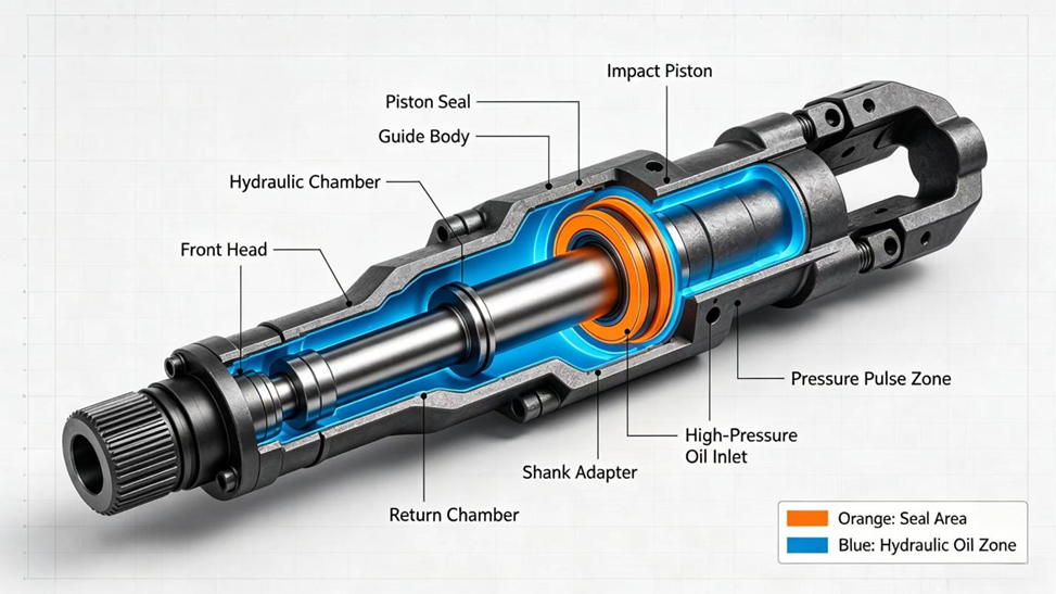
The impact piston is the part of a hydraulic rock drill that does the work: it is driven back and forth at high frequency and strikes the shank adapter on every cycle. The seal that surrounds it has a hard job. It has to separate oil chambers that are operating at very different pressures, slide against a piston that is moving at speed, and survive pressure pulses that are generated by the percussion cycle itself. This article explains where the impact piston seal sits, how it works, why it fails, and what to check before you order a replacement. Where numbers are given, they come from published engineering studies of hydraulic rock drills; the sources are listed at the end.
What Is an Impact Piston Seal in a Hydraulic Rock Drill?
An impact piston seal is a dynamic seal fitted in the guide body or cylinder bore around the percussion (striking) piston. It keeps hydraulic oil from passing along the piston from one working chamber to the next, so that pressure can be built up on the correct side of the piston and the piston is driven as intended.
Catalogs and workshops use several names for this part, and they are not always used consistently: percussion piston seal, striking piston seal, piston guide seal, and, on hydraulic breakers, main seal. Because some of these names are also used for other seals on the machine, always confirm the position of the seal, and not only its name, against the parts diagram for your drill model.
Where Does the Impact Piston Seal Sit, and What Does It Separate?
In published designs for hydraulic percussion apparatus, the seal sits in an annular housing cut into the guide body that surrounds the piston. It closes the small radial gap between the guide body and the piston, and so keeps oil from flowing between an annular channel on one side of the housing and an annular channel on the other. The exact arrangement differs between manufacturers and between models, and some drills use more than one piston seal along the piston, so the parts diagram for your own machine is the reference.
Seen from the seal's point of view, the working environment has three features: a piston surface that moves quickly in the axial direction, an oil film that is thin and constantly changing, and a pressure difference across the seal that changes with every blow.
One engineering description of a rock drill piston seal layout [1] shows the logic behind it. The piston is carried by sliding bearings at its two ends and hangs free in the middle of the cylinder, so it does not rub on the cylinder wall while it moves. For this to work, the largest clearance at the sliding bearing must stay smaller than the smallest clearance at the cylinder:
xh,max < xg,min → ESh − eih < EIg − esg (1)
Here x is a radial clearance, h refers to the sliding bearing and g to the cylinder, ES and EI are the upper and lower deviations of a bore, and es and ei are the upper and lower deviations of the piston diameter at that location. The same source recommends an H5/f5 fit between the bearing and the piston, an H7/e7 fit between the piston and the cylinder, three to four shallow ring grooves to relieve sliding pressure, a cylinder roundness better than 0.003 mm, and an oil-impregnated powder-metallurgy bearing material. In that layout the close fits act as a clearance seal, and two Step seals are fitted in series behind it as the last seal on the leakage side, with their grooves 5 to 20 mm apart, so that no oil escapes to the outside. These are values from one published description, dated 2003, and individual drills differ.
How Does the Impact Piston Seal Work While the Piston Strikes?
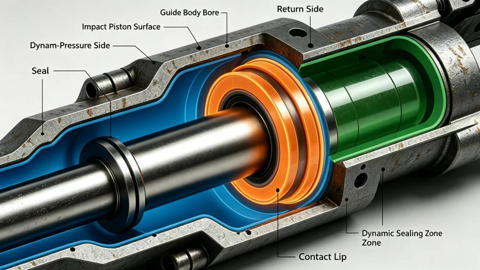
The seal does not work by being rigid. It works by keeping a controlled contact with the piston surface that is tight enough to resist oil flow and loose enough to let the piston slide with an acceptable amount of friction. A thin oil film remains between the seal lip and the piston, which lubricates and cools the contact.
This balance is delicate in a percussion unit. If the contact is too loose, oil leaks across the seal and the percussion cycle loses efficiency. If the contact is too tight, friction and heat rise at the lip, which is the part of the seal that is most exposed to wear. That is why seal construction, lip shape, and material are chosen together for each drill model rather than treated as interchangeable details.
The balance can be written down. Oil crosses the thin annular gap along a piston in two ways: pressure-driven flow, caused by the pressure difference across the gap, and shear-driven flow, dragged along by the moving piston surface. For a rock drill piston, the leakage flow q and the resulting power loss P can be written as [2]:
q = π d [ Δp δ3 / (12 μ L) ± δ vp / 2 ] (2)
P = π d (Δp)2 δ3 / (12 μ L) + π d μ L vp2 / δ (3)
In these expressions d is the piston diameter at the gap, δ the radial clearance, L the length of the sealing land, μ the dynamic viscosity of the oil, Δp the pressure difference and vp the piston speed. The sign in the flow equation depends on whether the piston moves with or against the pressure-driven flow. The first term of the power loss is leakage and grows with the cube of the clearance. The second term is viscous friction and shrinks as the clearance opens. Their sum therefore has a minimum, and a clearance that is either too tight or too open wastes energy. In the study behind these equations, the lowest total loss for a drill supplied at 14 to 18 MPa occurred at a diametral clearance of roughly 0.05 to 0.06 mm. The model was checked against a leakage test at 10 MPa, where the whole impact system leaked 1.5 L/min with the piston at the start of its return stroke and 0.8 L/min at the start of the stroke, and the simulation agreed within 17% [2]. That clearance belongs to the piston and guide, not to the seal, but it sets how much sealing work is left for the seal behind it.
The seal itself adds friction to the piston. In the same force balance, the seal resistance is [2]:
Ff = π b f ( d1 p1 + d2 p2 ) (4)
where b is the seal width, f the friction coefficient between seal and piston, d₁ and d₂ the sealed diameters, and p₁ and p₂ the pressures in the front and rear chambers. Because the pressure appears in the equation, a high-friction seal wastes the most energy exactly when the drill is working hardest.
The oil film itself follows the Reynolds equation of hydrodynamic lubrication. A study of rubber-energized piston seals in hydraulic cylinders [3] derives the film thickness left behind on the moving surface and the resulting leakage per stroke:
ho = √[ 2 μ u / ( 9 G ) ] (5)
Q = ( √2 / 3 ) π D L [ √( μ uo / Go ) − √( μ ui / Gi ) ] (6)
Here u is the sliding speed, G is the largest contact-pressure gradient dP/dx at the oil side of the seal, D is the piston diameter, L the stroke, and the subscripts o and i mean the outward and inward strokes. A steeper contact-pressure gradient leaves a thinner film and less leakage, and a flatter gradient leaves more oil behind, which is one reason a worn seal with a flattened contact profile leaks more. That study analyzed seals in hydraulic cylinders and not rock drill pistons, so it is best read as an explanation of the mechanism and not as a source of numbers for a drill.
Why Are Pressure Peaks So Hard on an Impact Piston Seal?
In a percussion unit the oil does not move steadily. It is accelerated and stopped many times every second as the piston reverses, so the pressure at the seal is not a constant value but a pulsating one. Published patent literature on sealing devices for hydraulic percussion apparatus describes strong pressure peaks, caused by the fast reciprocating movement of the fluid, that can break the sealing lip and cause leakage.
Simulations and tests of working drills give an idea of how large the peaks can be. In a model of a dual-chamber-controlled rock drill supplied at 15 MPa, the front chamber peaked at 25.2 MPa after the impact, and the rear chamber peaked at 25.3 MPa when the control spool crossed its dead zone and suddenly connected the chamber to the supply, about 1.7 times the supply pressure, followed by decaying oscillation [2]. In a prototype test supplied at 18 MPa, the pressure in the primary buffer chamber climbed from about 8 MPa to a working level of 18 to 20 MPa, with short peaks that reached the order of 40 MPa on each blow [4].
The gas in the buffer and accumulator behaves like a spring. When it is compressed quickly the process is close to adiabatic, and its stiffness depends on its charge:
p Vn = constant, k = n A2 p / V (7)
where p is the gas pressure, V the gas volume, A the effective area of the gas piston or diaphragm, k the gas-spring stiffness, and n the polytropic exponent, taken as 1.4 for the adiabatic case [4]. A stiffer gas spring cushions less and lets higher peaks through. In that prototype, a machining error in the position of the buffer return port cut the pre-opened flow area of the return throttle, raised the initial pressure and the gas-spring stiffness, and pushed the buffer piston toward a hard-spring, short-stroke, high-damping behavior, so the chamber pressure overshot. The authors recommend holding the port position within ±0.2 mm and its angle within ±1°. For a seal, the practical point is that the peaks it sees depend on parts that have nothing to do with the seal itself.
Field reports point the same way. In a rock drill maintenance case from a tunnel project, slow drilling and abnormal vibration of the percussion hose were traced to a failed inlet accumulator diaphragm, which the authors explain as the drill being unable to absorb the pressure peaks produced in service; the drill returned to normal after the accumulator was dealt with and its nitrogen charge was adjusted [5].
Frequency matters as much as amplitude. Percussion rates of about 40 to 50 blows per second are reported for one drill [2] and about 95 for another [6], and at 95 blows per second a seal sees roughly 340,000 pressure cycles in a single hour of drilling.
Peaks are harmful for two separate reasons. First, they load the lip suddenly, which is a very different kind of load from steady pressure. A transient simulation of a rubber ring under fast pressure switching between 5 and 25 MPa found micro-slip at the contact interface, a secondary contact-pressure peak on the low-pressure side during the rapid rise, and stress that kept changing after the pressure had stopped changing, because rubber is viscoelastic; all of these effects grew with the pressure amplitude and the rate of change [7]. Second, a peak briefly raises the pressure difference across the seal's clearance gap, and that is the condition under which a soft material tends to be pushed into the gap. The accumulator in the percussion circuit exists in part to reduce these pulsations before they reach the rest of the circuit, so a seal that fails repeatedly in a drill with a weak accumulator charge may be showing a problem that is not in the seal.
Why Do Many Impact Piston Seals Combine a Hard Ring With an Elastomer Energizer?
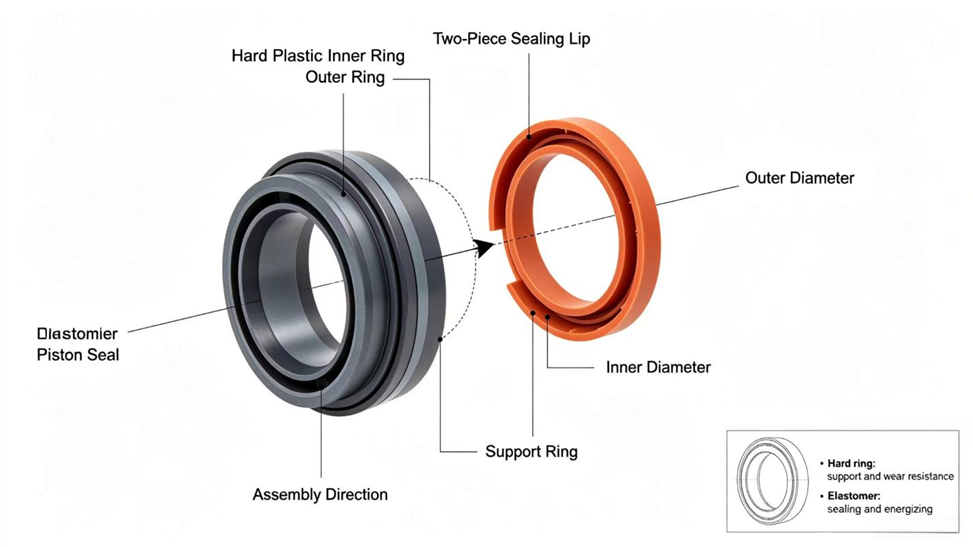
A common construction in published percussion-apparatus designs is a two-part seal. The inner ring, the part that touches the piston, is made from a hard, low-friction, Teflon-based plastic with a sealing lip. Around it sits an elastomer ring that presses the inner ring toward the piston and seals against the housing. Each material does the job it is best suited to: the plastic ring tolerates sliding contact and heat better, and the elastomer supplies the elastic preload that the plastic does not have on its own.
The Step seal described in rock drill literature [1] follows this pattern. Its sealing ring is a low-elasticity, low-friction material such as PTFE with additives, and the O-ring on the outside never touches the moving piston. The O-ring supplies the elastic force that presses the ring against the piston and makes up for the material the ring loses as it wears. The ring is directional, so it is installed with its stepped face toward the pressure. In that paper's test graphs the Step seal leaked far less than other molded packing types, with leakage rising only slightly with pressure, on the order of 0.005 to 0.01 mg per cycle up to 30 MPa. Its friction coefficient stayed in the range of about 0.02 to 0.04 and was almost flat as speed increased, with start-up friction lower than running friction, so the stick-slip crawling typical of rubber seals at low speed was avoided. Compared with a rubber lip seal at the same pressure and speed, its friction force was much lower and rose much less with pressure [1].
For any self-energized seal of this type the sealing condition is that the contact pressure along the sealing band must exceed the pressure of the oil being sealed:
pc(x) ≥ pm (8)
Finite-element work on rubber-energized piston seals [3] shows how design parameters move this balance. At a given medium pressure, a larger groove-edge chamfer raises the contact pressure and the start-up friction and reduces leakage. A wider groove, a deeper groove, or a larger sealing gap lowers the contact pressure and the start-up friction and increases leakage. And a higher medium pressure thickens the film, raises the contact pressure, and reduces leakage. Low friction and low leakage pull against each other, and the construction is a compromise between them. High equivalent (von Mises) stress in the rubber also matters, because it speeds stress relaxation and can start cracks.
The same patent literature describes why single-piece designs have limits. A one-piece U-shaped seal rubbing on the piston can heat the inner lip enough to destroy it, and in rotary-percussive drills, where the piston can rotate without moving axially, the lip may receive too little lubrication and wear out quickly. Some designs add a protective profile on the inner ring that shapes the flow passage next to the piston, with the intention of slowing the oil and damping pressure peaks before they reach the lip. Not every drill uses such a design, and which construction is fitted to your machine is a model-specific question.
What Happens When an Impact Piston Seal Fails?
When the lip wears, hardens, or breaks, oil can bypass the seal. The drill may continue to run, but the percussion cycle becomes less efficient because pressure is lost across the worn seal, and the extra internal leakage turns into heat in the oil. The power lost to leakage is simply the leakage flow multiplied by the pressure drop [2]:
Pq = q · Δp (9)
As an illustration, the test drill described above leaked 1.5 L/min through its whole impact system at 10 MPa. 1.5 L/min is 2.5 × 10⁻⁵ m³/s, so the power lost as heat is about 2.5 × 10⁻⁵ × 10 × 10⁶ ≈ 250 W. This figure is for the whole system and not for the piston seal alone, but it shows how quickly leakage becomes heat in a small, hard-working machine.
Depending on the design, a failed piston seal can also allow oil to move into a chamber where it should not be, which is a different kind of problem and may affect other seals. In one maintenance report, a drill whose percussion had stopped was found to have milky hydraulic oil, and the cause was traced to a failed impact piston seal [5].
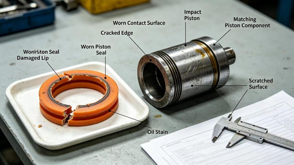
Fragments of a broken seal can enter the oil and travel through the circuit. This is the reason a seal failure is treated as a contamination event as well as a leakage event: the oil and the filter should be checked, not only the seal replaced.
How Can You Tell Whether the Impact Piston Seal Has Failed?
No single symptom proves a seal failure. The signs below are observations that point toward the seal and should be confirmed by inspection and by the checks in your service manual.
Observation |
What It May Indicate |
Next Check |
Lower impact energy or slower percussion with normal pump flow |
Internal leakage past the piston seal, or a weak accumulator charge |
Check accumulator pre-charge first, then inspect the seal |
Oil temperature rising faster than usual |
Extra internal leakage turning into heat, or high friction at the lip |
Check cooling circuit, then compare the seal contact surface |
Oil leaking at the front of the drill |
A different seal in the front head, or a failed piston seal with oil bypass |
Identify the leak path before ordering parts |
Black or plastic particles in the oil or filter |
Seal lip breaking up |
Inspect the seal, flush the circuit, replace the filter |
Scoring or discoloration on the piston |
Dry running, contamination, or overheating at the contact |
Inspect the piston surface before fitting a new seal |
Several of these observations have causes outside the seal, which is why the next check column starts with the circuit rather than with the part.
What Causes Premature Impact Piston Seal Wear?
The following conditions are known to shorten the life of a dynamic seal in a percussion unit. Some may act together:
- Pressure peaks that exceed what the seal construction was designed to take, often traced to a weak or incorrectly charged accumulator.
- Poor lubrication or cooling at the lip, particularly in rotary-percussive units where the piston rotates without translating.
- Oil that is contaminated or overheated, which accelerates wear and hardens elastomers.
- A piston surface that is scored, pitted, or has lost its finish, which wears the lip as the piston moves.
- Excessive clearance between piston and guide body from bore or bushing wear, which allows a soft material to be pushed into the gap.
- Installation damage, such as a lip nicked or rolled while the seal was fitted over sharp edges.
Clearance and pressure are linked. The Step seal source [1] lists a maximum diametral clearance, the gap the seal could be pushed into, that becomes tighter as pressure rises. For rod diameters of 30 to 36 mm, it is 0.6 to 0.3 mm up to 20 MPa and 0.3 to 0.2 mm between 20 and 40 MPa; for 38 to 50 mm it is 0.8 to 0.4 mm and 0.4 to 0.2 mm. Wear of the guide or the piston can move a seal's gap out of this kind of window without any change to the seal. These values are given as an example of how the limit behaves, and the limit for your own drill is the manufacturer's.
Maintenance experience points in the same direction. A rock drill fault analysis [8] attributes seal failures mainly to poor seal quality, damage during installation, and unsatisfactory machining of the seal groove, and recommends that seals and bushings are fitted with special tools so that they are not damaged on the way in.
What Should You Check Before Replacing the Seal, and How Do You Choose the Right One?
Replacing the seal without finding the cause usually repeats the failure. Before ordering, work through these checks in order:
- Confirm the drill model and serial information, and identify the seal position on the parts diagram.
- Check the accumulator pre-charge and the oil condition, since both change the load on the seal.
- Inspect the piston surface and the guide body bore for scoring, wear, or damaged edges.
- Measure the clearance between piston and guide, and compare it with the manufacturer's limit for your working pressure.
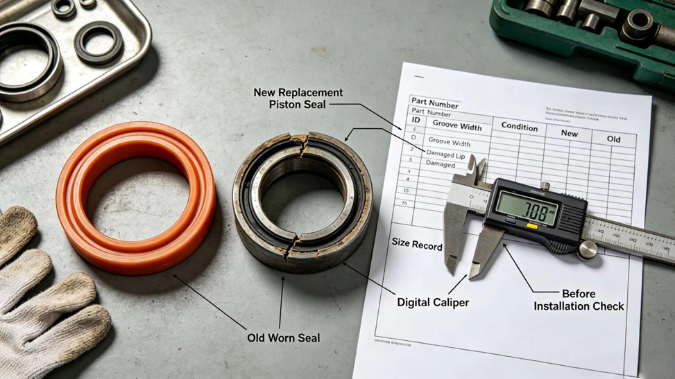
- Measure or record the old seal's dimensions and profile, and keep the failed seal for comparison.
- Stop and consult the manufacturer's service procedure for disassembly of the percussion unit; this is model-specific and the circuit must be depressurized first.
When you select the replacement, three points decide the result:
- Identity: the replacement must match the OEM part number or the verified dimensions and profile. A seal that is close is not the same as a seal that fits.
- Construction: if the original is a two-part seal, the replacement should be the same construction, not a single-material ring in the same size.
- Material: the hard ring and the elastomer must suit the oil and the temperature of the drill. This is covered in the companion article on impact piston seal materials.
Where Can You Source a Reliable Replacement Impact Piston Seal?
Because impact piston seals are specific to each drill model, matching normally starts from the OEM part number, a drawing, or the worn part itself, not from a general description.
Nanjing Hovoo Machinery Technology Co., Ltd, a Chinese sealing manufacturer founded in 2013, produces PU, rubber, and PTFE sealing components, including piston seals, rod seals, and seal kits, and has a product range for hydraulic rock drills. The company states that it offers free technical support. If you are not sure which seal your drill needs, you can send the rock drill model, the OEM part number if you have it, the dimensions or a drawing, photographs of the worn seal, and your operating conditions, and ask the supplier to review the seal construction and material before an order is placed.
Selected technical references consulted for this article:
- Li Chuan, Yan Tianjun, Li Tiehui. Impact piston sealing and the Step seal of hydraulic rock drills. Rock Drilling Machinery & Pneumatic Tools, 2003, (3): 8–12. (In Chinese)
- Wang Jiansen, Yan Hongliang, Zhang Xin, Wang Yanjun, Liu Bin, Wei Liejiang. Optimal clearance design between impact piston and cylinder of a dual-chamber-controlled hydraulic rock drill. Chinese Hydraulics & Pneumatics, 2025, 49(4): 79–91. (In Chinese)
- Han Xiaoxia. Influence of hydraulic cylinder piston seal structure on start-up pressure and internal leakage. Master's thesis, Lanzhou University of Technology, 2016. (In Chinese)
- Wang Jiansen, Yang Guangsheng, Liu Shaojun, Feng Huai, Wen Yongqiang. Analysis of the overpressure phenomenon in the primary buffer chamber of a dual-chamber-controlled hydraulic rock drill. Chinese Hydraulics & Pneumatics, 2026, 50(7): 57–67. (In Chinese)
- Hu Jiangtao. Design and fault handling of hydraulic rock drills. Mechanical and Electrical Information, 2021, (8): 58–60. (In Chinese)
- Yang Mingming. Experimental study on the impact performance of a hydraulic rock drill. Equipment Management and Maintenance, 2025, (10). (In Chinese)
- Yuan Xiaoming, Zheng Ze, Chen Haimin, Li Yongqi, Wang Weiwei, He Shixing. Simulation study on an O-type static sealing ring under pulse pressure. Hydraulics Pneumatics & Seals, 2026, online first. (In Chinese)
- Liu Jiankui, Fu Yuehua, Zhou Shijie. Analysis and countermeasures for common faults of hydraulic rock drills. Rock Drilling Machinery & Pneumatic Tools, 2020, (4): 59–61. (In Chinese)
Table of Contents
- What Is an Impact Piston Seal in a Hydraulic Rock Drill?
- Where Does the Impact Piston Seal Sit, and What Does It Separate?
- How Does the Impact Piston Seal Work While the Piston Strikes?
- Why Are Pressure Peaks So Hard on an Impact Piston Seal?
- Why Do Many Impact Piston Seals Combine a Hard Ring With an Elastomer Energizer?
- What Happens When an Impact Piston Seal Fails?
- How Can You Tell Whether the Impact Piston Seal Has Failed?
- What Causes Premature Impact Piston Seal Wear?
- What Should You Check Before Replacing the Seal, and How Do You Choose the Right One?
- Where Can You Source a Reliable Replacement Impact Piston Seal?


