33-99 Не. Муфу Ерд. Глуоу округ, Нанкинг, Кина [email protected] | [email protected]
33-99 Не. Муфу Ерд. Глуоу округ, Нанкинг, Кина [email protected] | [email protected]

Теоретски, сваком хидрауличком слојачу стене потребан је акумулатор променљивог притиска посебно велики акумулатор високог притиска.
Аккумулатор високог притиска, инсталиран на улазу система хидрауличног ломача стене, служи три сврхе:
(1) Избалансирање вишка и дефицита снабдевања система и потрошње нафте. Када је испуштање пумпе веће од потрошње уља система, акумулатор високог притиска апсорбује вишак испуштања и делује као уређај за складиштење уља. Када је испуштање пумпе мање од потрошње уља система, испушта уље да би допунио дефицит, делујући као уређај за испуштање уља. Акумулатор високог притиска игра улогу балансирања вишка и дефицита проток у систему, и важна је компонента за стабилан рад система.
(2) За апсорбоцију флуктуација притиска система и смањење малих притиска, заштиту цеви и хидрауличких компоненти и повећање њиховог живота.
(3) У пројектовању хидрауличких механизама удара користећи теорију апстрактних променљивих, помаже у остваривању еквивалентне силе. Док је акумулатор правилно дизајниран, може се добити тачна еквивалентна сила, што осигурава да систем постиже потребну кинематику и динамику.
С обзиром на важну улогу акумулатора високог притиска у хидрауличном систему за кршење стене и посебно на његову посебну функцију осигурања да систем постиже потребну кинематику и динамику утврђивање исправне теорије и методе пројектовања акумулатора високог притиска је веома
Ефикасан запремину испуштања је важан параметар перформанси акумулатора и такође основа за рачунање пројектовања акумулатора. Када хидраулички рушилац стене ради у стационарном стању, максимална количина уља коју акумулатор чува и испушта у једном циклусу назива се ефективна количина испуштања, означена Δ V .
Ефикасан обим испуштања Δ V је повезана са кинематичким карактеристикама. Када је проток пумпе фиксиран и структура хидрауличког кршилака и кинематика фиксирани, енергија удара Š H , фреквенција f H , и ефикасан запремину испуштања Δ V све су обавезно фиксиране. Дакле, када се дизајнира акумулатор, ефикасан обим испуштања је већ познат. Како израчунати Δ V ће бити уведена у каснијим поглављима.
Основа за израчунавање ефикасне запремине акумулатора V a је њен стварни ефикасан запремину испуштања Δ V - Да ли је то истина? Када Δ V ради унутар акумулатора то нужно узрокује систем притисак уља да се промени, а еквивалентна сила F g мора бити одржаван. Због тога, треба проучавати методу израчунавања пројекта акумулатора која задовољава горе наведене захтеве. Дијаграма притиска (силе) области акумулатора током рада приказана је на листу 3-2.
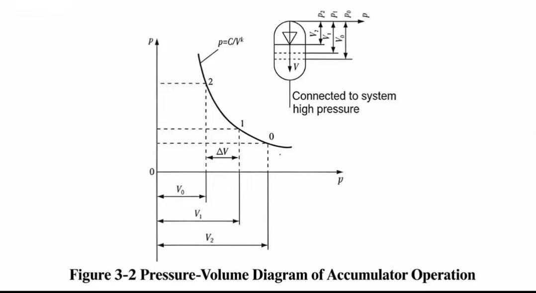
Иако радна фреквенција хидрауличног ломача не је веома висока, процес компресије и експанзије азота у њему је такође прилично брз, са недостатком времена за размену топлоте са околином; стога се може третирати као адиабатни процес. Из једначине стања гаса:
p 1V k 1 = p 2V k 2 = p a V k a (3.12)
где: p a притисак наплате, односно притисак запечаћеног гаса;
V a обим наплате, тј. обим акумулатора када је клип у тачки удара (општено максимални радни обим V амакс );
p 2 максимални радни притисак;
V 2 волумен који одговара p 2(општено минимални радни обим V 2 минута );
p 1 минимални радни притисак;
V 1 волумен који одговара p 1, V 1 < V a .
У еквиваленту. (3.12), k = 1,4 је адиабатни експонент. Јасно је:
δ V = V 1 − V 2 (3.13)
Из Еквилатора. (3.12):
V 1 = V a (p a / p 1)1/K (3.14)
V 2 = V 1 (p 1 / p 2)1/K (3.15)
Замена у еквилацију. (3.13) даје:
δ V = V a (p a / p 1)1/K [1 − 1 / ( p 2 / p 1)1/K ] (3.16)
У еквиваленту. (3.16), нека p a / p 1 = a = 0,8 до 1; и однос радног притиска гаса γ = p 2 / p 1, обично γ = 1,2 до 1,45, изабран на основу радних карактеристика хидрауличког ломача. Када a = 1, минимални радни притисак клизма једнак је притиску за напајање ( p a = p 1); у овом стању V 1 = V a - Да ли је то истина? Да би се спречило да се мембрана акумулатора додирне са основом при минималном радном притиску хидрауличког кршила што би скраћено трајање рада a треба да буде мање од 1.
Постоје два разлога за избор γ : када γ је велика, јер акумулатор ради у адиабатном стању, температура се снажно повећава, што може изазвати прерано погоршање мембране акумулатора или чак га изгорети; али повећање γ може ефикасно смањити ефикасан запремину V a аккумулатора, што је веома корисно за смањење структурне величине акумулатора. Проектант мора претежити предности и мане и одлучити на основу услова за примену; стога:
δ V = V a a 1/K (1 − 1 / γ 1/K ) (3.17)
Из Еквилатора. (3.17) могу се наћи ефективни запремину акумулатора:
V a = Δ Вγ 1/K / [ a 1/K (γ 1/K - 1)] (3.18)
ИК. (3.18) показује да, од ефективног запремине испуштања Δ V , одговарајући обим наплате може се наћи, како би се осигурало да се пројектована кинематика и Δ V постигнуте. У пракси, ефикасан запремину испуштања Δ V је уље које акумулатор допуњава у упис током струје, како би надокнадио недовољну залиху пумпе.
За пројектно израчунавање ефективног запремине испуштања Δ V , погледајте одељак 7.5. Да би се задовољили захтеви оптималног пројектовања, за различите пројектоване циљеве, израчунавање ефективног запремине испуштања Δ V промени са изабраним α у (види одељке 7.2.5 и 7.27а).
У овом тренутку, иако V a ако је пронађен и може се користити за пројектовање структурних параметара акумулатора, задатак пројектовања за рачунање акумулатора још није завршен. Најкритичније питање је како контролисати притисак уља како би се осигурало да се постигне еквивалентна сила; и само постизањем еквивалентне силе може се гарантовати дизајнирана кинематика, која заузврат гарантује Δ V - Да ли је то истина? Другим речима, постоји одговарајући однос између Δ V i F g .
Мора се истаћи да када V a је фиксна вредност, p 1, p 2, i p a може имати многе комбинације, остварујући више еквивалентних снага, више динамике и више кинематике тј. више Δ V вредности. Следећи задатак је, да се даде фиксна V a , да би се пронашла комбинација p 1, p 2, i p a који могу постићи потребну еквивалентну снагу F g и Δ V - Да ли је то истина? Јер када p a промене, Š H , f H , Δ V , p 1, i p 2све се мења у складу са тим. Другим речима, мора бити притисак наплате p a који може гарантовати постизање еквивалентног притиска p g ... и не само. Наравно, основа за проналажење p a is p 1i p 2, тј. еквивалентни притисак p g ... и не само. Када се разумеју односи између ових параметара, метода за проналажење p 1, p 2, i p a од еквивалентног притиска p g може се проучавати.
Слика 3-2 описује p –V дијаграма акумулатора високог притиска током рада. На основу овог дијаграма, и комбинујући са принципом еквивалентне силе рад који ради променљива сила једнак је раду који ради еквивалентна сила имамо:
p g δ V = ∫ В2 В1 p d V (3.19)
У еквиваленту. (3.19):
p = C / V k
Замена у еквилацију. (3.19) и интегрисање:
p g δ V = C ∫В2 В1 d V / V k = 1 / (1 − k ( p 1V k 1V 1−к 1 − p 2V k 2V 1−к 2) (3.20)
Зато:
p g δ V = 1 / (1 − k ( p 1V 1 − p 2V 2) (3.21)
Елиминисање V 1i V 2путем замене и замене Ек. (3.17) даје:
p g = p 1/ ( k - 1) · ( γ − γ 1/K (Одговорно) γ 1/K − 1) (3.22)
Након прераспоређивања:
p 1 = p g (k - 1) ( γ 1/K - 1) / ( γ − γ 1/K ) (3.23)
У еквиваленту. (3.23) p g је еквивалентни притисак који се примењује на лице пистона које подстиче притисак. Узимајући у обзир губитке притиска у систему, треба их изразити као номинални притисак у систему p g = p H / K . p 1i p 2добијена на овај начин ће бити ближе стварним вредностима. Зато:
p 1= ( p H / K )(k − 1) γ 1/K - 1) / ( γ − γ 1/K ) (3.24)
p 2 = γп 1 (3.25)
p a = ап 1 (3.26)
У еквиваленту. (3.24) коефицијент отпора који рачуна о губицима притиска у систему је K = од 1,1 до 1.2.
Када акумулатор високог притиска хидрауличног ломача корака ради на овим параметрима, он гарантује да се постигне еквивалентан ефекат покрета снаге, да се реализује дизајнирана кинематика и да се испоручују потребне енергије удара и фреквенција удара. На овај начин се поједноставља сложен проблем израчунавања и нелинеарни проблем је линеарни.
На основу горе наведеног, хидраулички ударни уређај (хидрауличка бушилица и хидраулички рушилац) нелинеарни систем претвара се у линеарни систем. Из теоријске перспективе, клип може се кретати преко потеза S према било ком обрасцу, све док се може контролисати и достиже потребну максималну брзину у тачки удара v m све ово је изводљиво. За сваки образац покрета клизма мора постојати одговарајући образац варијације снаге; ова два су повезана као узрок и ефекат. Другим речима, без обзира на образац кретања који има упис, одговарајући образац варијације снаге мора се применити на њега сила је узрок, кретање је ефекат.
Наравно, након дизајнирања оптималног обрасца покрета, такође се може наћи одговарајући обрасц варијације снаге, чиме се подижу две теоријске теме за истраживање хидрауличних кршилача стене: кинематика и динамика хидрауличног кршилаца стене.

Добродошли у Хову, кинеску фабрику за тюлени. Производња ПУ, гумених и ПТФЕ пломби. Запечати укључују О-прстен, пистолни запечати, штапни запечати, сиви прстен и гасни запечати.


 EN
EN
 AR
AR CS
CS DA
DA NL
NL FI
FI FR
FR DE
DE EL
EL IT
IT JA
JA KO
KO NO
NO PL
PL PT
PT RO
RO RU
RU ES
ES SV
SV TL
TL IW
IW ID
ID LV
LV SR
SR SK
SK VI
VI HU
HU MT
MT TH
TH TR
TR FA
FA MS
MS GA
GA CY
CY IS
IS KA
KA UR
UR LA
LA TA
TA MY
MY