33-99No. Mufu E Rd. Gulou District, Nanjing, China [email protected] | [email protected]
33-99No. Mufu E Rd. Gulou District, Nanjing, China [email protected] | [email protected]

Een hydraulische rotsbreekmachine heeft vele constructievormen. Uitgaande van het werkingsprincipe, abstracteren en samenvatten de auteurs de meest fundamentele en meest kritische ideeën van een hydraulische rotsbreekmachine, en reduceren deze tot drie basiswerkingsmodi: zuiver hydraulisch, hydraulisch-pneumatisch gecombineerd en stikstof-explosief.
Het zuiver hydraulische werkingprincipe kent drie uitvoervormen: constante druk in de voorruimte / variabele druk in de achterruimte (afgekort als 'principe van constante druk in de voorruimte'), constante druk in de achterruimte / variabele druk in de voorruimte (afgekort als 'principe van constante druk in de achterruimte') en variabele druk in zowel de voor- als de achterruimte (afgekort als 'principe van variabele druk').
(1) Principe van constante druk in de voorruimte
Dit was het werkingprincipe dat aanvankelijk werd toegepast bij de start van de ontwikkeling van hydraulische rotsbreekmachines; alle latere technische verbeteringen zijn hierop gebaseerd. De hydraulische rotsbreekmachine met constante druk in de voorruimte is weergegeven in figuur 2-1.
Uit fig. 2-1 blijkt dat het systeem bestaat uit een cilinderlichaam, een zuiger, een regelklep en oliekanalen. Het cilinderlichaam en de zuiger vormen het slagmechanisme. De zuiger beweegt heen en weer binnen het cilinderlichaam, aangedreven door hydraulische olie, waardoor slagenergie extern wordt afgegeven en een grote slagkracht op het doel wordt uitgeoefend, wat een hamereffect veroorzaakt. De functie van de regelklep is om de olie die de zuiger aandrijft, van richting te laten veranderen, zodat een periodieke heen-en-weerbeweging van de zuiger wordt bereikt.
De hydraulische rotshamer weergegeven in fig. 2-1 heeft zijn zuiger op het slagpunt; de klepschijf bevindt zich in de positie waarin deze net is overgeschakeld van de arbeidsslag naar de terugslag. Op dit moment stroomt hogedrukolie via de constante hogedrukpoort van de klep naar de constante hogedrukruimte (kamer een ) van de cilinder, waardoor de zuiger tijdens de terugslag (naar rechts) wordt aangedreven. De olie in de variabele-drukruimte van de zuiger (kamer b ) wordt via poort 4 en de variabele-druk-/retouroliepoort van de klep teruggevoerd naar de tank. Wanneer de zuiger terugbeweegt totdat zijn voorste schouder poort 2 op het cilinderlichaam passeert, wordt olie onder hoge druk naar de duwkleppoort 5 geleid, waardoor de klep schakelt (naar links). Omdat de constante hoogdrukkamer van de klep nu is verbonden met de tussenliggende variabele-druk-kamer, stroomt olie onder hoge druk de achterkamer van de zuiger binnen b via poort 4. Beide zijden van de zuiger staan nu onder olie onder hoge druk, maar omdat het drukdragende oppervlak van de achterkamer b groter is dan dat van de voorkamer een de zuiger begint te vertragen tijdens de terugslag, zijn snelheid daalt tot nul en hij begint de arbeidsslak (naar links). Wanneer de centrale inkeping van de zuiger de openingen 2 en 3 verbindt, heeft de zuiger net het slagpunt bereikt, waarmee één cyclus is voltooid; tegelijkertijd wordt de drukklepopening 5 verbonden met de retourolieleiding, zodat de spil naar rechts schakelt en terugkeert naar de positie die is weergegeven in fig. 2-1, waarmee één volledige cyclus is voltooid en de zuiger zich voorbereidt op de volgende terugslag. Op deze manier realiseert de zuiger een continue slagwerking en levert voortdurend slagenergie. Luchtkamer c in dit werkingprincipe wordt aan de atmosfeer ontlucht. 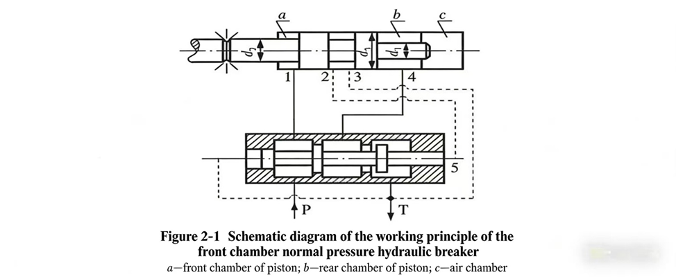
(2) Constantedrukprincipe voor de achterkamer
Er dient op gewezen te worden dat dit werkingprincipe alleen kan worden gerealiseerd op voorwaarde dat het drukdragend oppervlak van de voorste kamer van de zuiger een groter is dan dat van de achterkamer b , d.w.z. de diameter van de voorste kamer van de zuiger is kleiner dan de diameter van de achterkamer ( d 1 > d 2).
Figuur 2-2 toont het schema van een hydraulische rotshamer met constante druk in de achterkamer en variabele druk in de voorkamer.
Vergeleken met figuur 2-1 is het enige verschil dat aansluiting 1 op het cilinderlichaam is verbonden met de variabel-druk-kamer van de klep in plaats van met de constante-druk- (hoogdruk-)kamer; aansluiting 4 is rechtstreeks verbonden met de constante-druk-kamer van de klep; alle andere oliekanalen zijn identiek. Figuur 2-2 toont het moment waarop de krachtstroke van de zuiger net is beëindigd en de klep reeds is geschakeld — het systeem bevindt zich op het tijdstip waarop de terugstroke begint.
Het werkingskenmerk van dit principe is dat de hydraulische rotshamer tijdens de terugstroke geen olie afvoert, maar wel olie afvoert tijdens de krachtstroke; en het drukdragend oppervlak van de voorkamer een groter is dan dat van de achterkamer b omdat de ontlasttijd van de arbeidsslag kort is en de stroming groot, zijn de hydraulische drukverliezen bij dit principe groter dan bij het principe van constante druk in de voorruimte. Momenteel gebruiken de meeste hydraulische rotshamer dit principe niet. 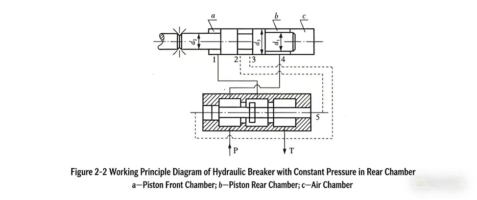
(3) Principe van variabele druk in voor- en achterruimte
Het principe van variabele druk in voor- en achterruimte is weergegeven in figuur 2-3. Uit dit schema blijkt duidelijk dat dit type hydraulisch slagapparaat een complexe constructie heeft met veel kanalen, wat de productiekosten verhoogt. Daarom wordt dit principe tegenwoordig niet gebruikt in hydraulische rotshammers; het wordt nog steeds toegepast op sommige merken hydraulische rotboorapparaten.
Figuur 2-3 toont de positie aan het einde van de arbeidsslag van de zuiger en het begin van de terugslag. Wanneer de terugslag begint, stroomt olie onder hoge druk uit de middenruimte van de klep via de linker ruimte en de cilinderopening 1 naar de voorruimte van de zuiger een en duwt de zuiger naar rechts. De olie in de achterruimte b wordt via cilinderpoort 5 en de rechterkamer van de klep in de oliebak geleid. Tijdens de terugslag, wanneer de linker schouder van de zuiger poort 2 op het cilinderlichaam passeert, duwt olie onder hoge druk via poort 7 de klepschuif naar rechts; de klepschuif schakelt onmiddellijk de toevoer- en afvoeroliepaden van het cilinderlichaam om — cilinderpoort 5 komt onder hoge druk te staan en cilinderpoort 1 wordt verbonden met de oliebak voor terugvoer — waardoor de zuiger begint te vertragen, zijn snelheid snel daalt tot nul en hij overgaat op versnelling tijdens de krachtslag. Wanneer de krachtslag van de zuiger het slagpunt bereikt, maakt de centrale inkeping van de zuiger verbinding tussen cilinderpoorten 2 en 3, terwijl poorten 4 en 5 ook met elkaar verbonden worden; de linkerkant van de klepschuif is via poort 7 verbonden met poorten 2 en 3 voor olieafvoer, en de rechterkant van de klepschuif (poort 6) is via poorten 4 en 5, de rechterkant van de klep en de tussenkamer verbonden met de hoge-drukzijde, waardoor de schuif naar links schakelt, de toevoer- en afvoeroliepaden van de cilinder wijzigt en één werkcyclus van de zuiger voltooit. De zuiger en de klepschuif van het hydraulische slagapparaat keren terug naar de toestand weergegeven in figuur 2-3 — het begin van de terugslag. Op deze manier levert de hydraulische rotsslagmachine, door de continue heen-en-weer beweging van de zuiger, voortdurend slagenergie naar buiten en voert effectief de slagwerkzaamheden uit. 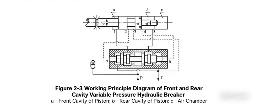
Alle drie de zuiver hydraulische werkwijzen die hierboven zijn beschreven, worden momenteel toegepast in hydraulische rotatiedraaiboren, hydraulische rotatiebrekers en andere hydraulische slagmechanismen, maar hydraulische rotatiebrekers maken nog steeds vaker gebruik van de gecombineerde hydraulisch-pneumatische werkwijze.
Uit de analyse van de zuiver hydraulische werkwijze blijkt dat alle slagenergie van een zuiver hydraulisch slagmechanisme wordt geleverd door het hydraulische systeem. Naarmate het gebruik van zuiver hydraulische rotatiebrekers toenam en het onderzoek vorderde, bleek echter dat de hydraulische verliezen aanzienlijk waren, wat verdere efficiëntieverbetering beperkte. De olie die door de kanalen binnen het cilinderlichaam stroomt, moet wrijven tegen de wanden van de buis, en de hydraulische verliezen ten gevolge van bochten, diameterveranderingen en stroomrichtingswijzigingen zijn aanzienlijk; hoe groter de stroomsnelheid, des te groter de verliezen, en dit is vooral ernstig tijdens de arbeidsslag.
Op dit moment wordt het hydraulisch-pneumatische gecombineerde werkprijsipie voornamelijk gebruikt voor hydraulische rotsbreekmachines die grote slagenergie en lage frequentie vereisen, en voor hydraulische heimachines.
Om de efficiëntie te verbeteren, hebben mensen na uitgebreid onderzoek een eenvoudige en effectieve methode gevonden: het gebruik van gas en olie in combinatie om de slagenergie van de hydraulische rotsbreekmachine te leveren. Dit verlaagt de benodigde debietstroom tijdens de krachtstroke — waardoor hydraulische verliezen worden verminderd en de werkefficiëntie wordt verbeterd — vandaar de hydraulisch-pneumatische gecombineerde hydraulische rotsbreekmachine.
Het structurele principe van de hydraulisch-pneumatische gecombineerde hydraulische rotsbreekmachine is zeer eenvoudig: vul gewoon de luchtkamer. c volgens de drie zuiver hydraulische principes die hierboven zijn genoemd, met stikstof op een bepaalde druk. Omdat stikstof nu aanwezig is, wordt deze samengeperst wanneer de zuiger de terugslag uitvoert, waardoor energie wordt opgeslagen; tijdens de krachtslag wordt deze energie samen met de olie vrijgegeven om de zuiger te drijven, waardoor kinetische energie wordt verkregen op het impactpunt en deze wordt omgezet in impactenergie. Duidelijk is dat de rol van stikstof noodzakelijkerwijs de hoeveelheid olie vermindert die tijdens de krachtslag wordt gebruikt, wat het olieverbruik verlaagt en bijgevolg lagere hydraulische verliezen en een hoger rendement oplevert.
Vergeleken met een zuiver hydraulische rotshamer is het effectieve drukdragend oppervlak van de achterkamer van de zuiger b bij een hydraulisch-pneumatische gecombineerde hydraulische rotsbreekmachine wordt verlaagd. Deze vermindering van het effectieve drukdragende oppervlak betekent minder olieverbruik tijdens de krachtstroke en lagere hydraulische verliezen — dit is de belangrijkste reden waarom hydraulisch-pneumatische gecombineerde hydraulische rotsbreekmachines de afgelopen jaren snel zijn ontwikkeld. Hydraulisch-pneumatische gecombineerde hydraulische rotsbreekmachines maken bijna allemaal gebruik van het werkprijsipie van constante druk in de voorruimte; dit is ook een belangrijke kenmerk van het hydraulisch-pneumatische gecombineerde type.
Het werkprijsipie van een stikstof-explosieve hydraulische rotsbreekmachine verschilt niet fundamenteel van dat van een hydraulisch-pneumatische gecombineerde hydraulische rotsbreekmachine; de structurele parameters van de zuiger verschillen eenvoudigweg. Het belangrijkste verschil is dat de diameter van de voor- en achterzuiger gelijk is, d.w.z. d 2 = d 1, en alle slagenergie wordt geleverd door stikstof.
Gelijke zuigerdiameters aan de voor- en achterzijde zijn het belangrijkste kenmerk van de stikstof-explosieve hydraulische rotsonderbreker. Tijdens de arbeidsslag wordt er geen olie verbruikt in de achterkamer, en kan alle slagenergie worden geleverd door stikstof. Uiteraard wordt de opgeslagen energie van de stikstof tijdens de terugslag door de hydrauliek geleverd en omgezet in de kinetische energie van de arbeidsslag. Daarom is het uiteindelijk toch hydraulische energie die wordt omgezet — maar via compressie en energieopslag in een gasmedium wordt de opgeslagen stikstofenergie tijdens de arbeidsslag vrijgegeven en omgezet in mechanische energie van de zuiger.
Er dient op gewezen te worden dat alleen het constante-drukprincipe van de voorste kamer kan worden toegepast op de stikstof-explosieve hydraulische rotsbreekmachine; noch het constante-drukprincipe van de achterste kamer noch het variabele-drukprincipe van zowel de voorste als de achterste kamer kan worden toegepast op een stikstofhydraulische rotsbreekmachine. De reden hiervoor wordt duidelijk zodra u het kenmerk van de zuiger begrijpt dat d 2 = d 1.

Welkom bij HOVOO, een Chinese zegelfabriek. Productie van PU, Rubber en PTFE zegels. De zegels omvatten O-ring, pistonzegel, stangzegel, Gray ring en gaszegel.


 EN
EN
 AR
AR CS
CS DA
DA NL
NL FI
FI FR
FR DE
DE EL
EL IT
IT JA
JA KO
KO NO
NO PL
PL PT
PT RO
RO RU
RU ES
ES SV
SV TL
TL IW
IW ID
ID LV
LV SR
SR SK
SK VI
VI HU
HU MT
MT TH
TH TR
TR FA
FA MS
MS GA
GA CY
CY IS
IS KA
KA UR
UR LA
LA TA
TA MY
MY