33-99 நெர. முபு இி றூட். குலோ டிஸ்டிரிக்ட், நான்ஜிங், சீனா [email protected] | [email protected]
33-99 நெர. முபு இி றூட். குலோ டிஸ்டிரிக்ட், நான்ஜிங், சீனா [email protected] | [email protected]

ஒரு இயற்கை எண்ணெய் பாறை உடைப்பான் என்பது இயற்கை எண்ணெய் ஆற்றலை இயந்திர ஆற்றலாக மாற்றும் ஒரு தாக்கு இயந்திரமாகும். இது இரண்டு அடிப்படை இயங்கும் பாகங்களைக் கொண்டுள்ளது — ஒரு பிஸ்டன் மற்றும் ஒரு பரவல் வால்வு ஸ்பூல் — இவை ஒன்றுக்கொன்று மாற்று கட்டுப்பாட்டை செய்கின்றன: வால்வு ஸ்பூலின் முன்னும் பின்னும் நகரும் இயக்கம் பிஸ்டனின் மாற்று இயக்கத்தைக் கட்டுப்படுத்துகிறது, மேலும் பிஸ்டன் தனது ஒவ்வொரு ஓட்டத்தின் தொடக்கத்திலும் முடிவிலும் வால்வின் கட்டுப்பாட்டு எண்ணெய் கடத்தியைத் திறக்கவோ அல்லது மூடவோ செய்கிறது, இதன் மூலம் வால்வு மாற்று இயக்கம் நிகழ்கிறது — இவ்வாறு சுழற்சி நிகழ்கிறது… ஒரு இயற்கை எண்ணெய் பாறை உடைப்பானின் அடிப்படை இயங்கும் கொள்கை என்பது: இந்த பிஸ்டன்-ஸ்பூல் மாற்று கட்டுப்பாட்டின் மூலம், பிஸ்டன் இயற்கை எண்ணெய் (அல்லது வாயு) விசையின் கீழ் விரைவாக முன்னும் பின்னும் நகர்ந்து, சிசலைத் தாக்கி வெளிப்புறத்தில் வேலை செய்கிறது.
இயற்கை எண்ணெய் பாறை உடைப்பான்கள் பல்வேறு வகைகளிலும், வடிவங்களிலும் கிடைக்கின்றன, அவை பின்வரும் அத்தியாயங்களில் விரிவாக விளக்கப்படும். கீழே, முன்புற அறை மாறாத அழுத்தம் கொண்டும், பின்புற அறை மாறும் அழுத்தம் கொண்டும் இயங்கும் இயற்கை எண்ணெய் பாறை உடைப்பான் ஒன்று எடுத்துக்காட்டாக விளக்கப்படுகிறது, அதன் இயங்கும் கொள்கை விளக்கப்படுகிறது: 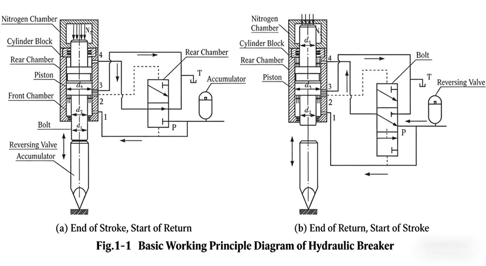
வரைபடத்தில் காட்டப்பட்டுள்ளது போல, திரும்பு ஓட்டம் (ரிட்டர்ன் ஸ்ட்ரோக்) தொடங்கும்போது, உயர் அழுத்த எண்ணெய் எண்ணெய் துளை 1 வழியாக பிஸ்டனின் முன் அறைக்குள் புகுந்து, ஒரே நேரத்தில் திசை மாற்று வால்வின் ஸ்பூலின் கீழ் முனையில் செயல்படுகிறது; இதனால் ஸ்பூல் வரைபடம் (அ) இல் காட்டப்பட்டுள்ள நிலையில் நிலையாக இருக்கிறது. இந்த நேரத்தில் பிஸ்டனின் முன் அறையில் உயர் அழுத்த எண்ணெய் இருக்கிறது; பின் அறை எண்ணெய் துளை 4 வழியாக திரும்பு எண்ணெய் (T) உடன் இணைக்கப்பட்டுள்ளது. முன் அறையில் உள்ள எண்ணெய் அழுத்தத்தால் இயக்கப்படும் பிஸ்டன், திரும்பு ஓட்டத்தின் போது முடுக்கமடைகிறது மற்றும் நைட்ரஜன் அறையில் சேமிக்கப்பட்டுள்ள நைட்ரஜனை (தூய ஹைட்ராலிக் வகையைத் தவிர) சுருக்குகிறது; அக்கியூமுலேட்டர் எண்ணெயைச் சேமிக்கிறது. பிஸ்டனின் திரும்பு ஓட்டம் கட்டுப்பாட்டு துளை 2ஐ அடையும்போது, உயர் அழுத்த எண்ணெய் ஸ்பூலின் மேல் முனையை அடைகிறது. இந்த நேரத்தில் ஸ்பூலின் மேல் மற்றும் கீழ் முனைகள் இரண்டும் உயர் அழுத்த எண்ணெயுடன் இணைக்கப்பட்டுள்ளன; வடிவமைப்பின்படி, ஸ்பூலின் மேல் முனையின் செயல்திறன் பரப்பு கீழ் முனையின் செயல்திறன் பரப்பை விட அதிகமாக இருப்பதால், உயர் அழுத்த எண்ணெயின் செயல்பாட்டால் ஸ்பூல் வரைபடம் (ஆ) இல் காட்டப்பட்டுள்ள நிலைக்கு மாறுகிறது. இந்த நேரத்தில் பிஸ்டனின் முன் மற்றும் பின் அறைகள் இரண்டும் உயர் அழுத்த எண்ணெயுடன் இணைக்கப்பட்டுள்ளன; அக்கியூமுலேட்டர் எண்ணெயை வெளியேற்றி அமைப்பிற்கு நிரப்புதலை வழங்குகிறது. கூட்டு விசை F_q இன் செயல்பாட்டால், பிஸ்டன் சக்தி ஓட்டத்தின் போது முடுக்கமடைகிறது, சிசலை (சிசல்) தாக்குகிறது மற்றும் தாக்க ஆற்றலை வெளியேற்றுகிறது. பிஸ்டன் தாக்கப் புள்ளியைக் கடந்தவுடன், கட்டுப்பாட்டு துளைகள் 2 மற்றும் 3 இணைந்து திரும்பு எண்ணெய் (T) உடன் இணைக்கப்படுகின்றன; வால்வு ஸ்பூலின் மேல் முனையில் உள்ள எண்ணெய் அழுத்தம் குறைகிறது; கீழ் முனையில் உள்ள எண்ணெய் அழுத்தத்தின் செயல்பாட்டால், வால்வு ஸ்பூல் விரைவாக வரைபடம் (அ) இல் காட்டப்பட்டுள்ள நிலைக்குத் திரும்புகிறது. மீண்டும் அசல் நிலைக்குத் திரும்பிய பின், பிஸ்டன் திரும்பு ஓட்டத்தைத் தொடங்குகிறது, அடுத்த தாக்க சுழற்சியில் நுழைகிறது, இது போன்று சுழற்சியாக தொடர்கிறது. இந்தச் செயல்முறையில், பிஸ்டன் மற்றும் வால்வு ஸ்பூல் இடையேயான இணைப்பு உறவு படம் 1-2 இல் காட்டப்பட்டுள்ளது. 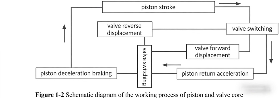
படம் 1-1 இலிருந்து, சக்தி ஸ்ட்ரோக் போது, பிஸ்டனின் எடை மற்றும் உராய்வு எதிர்ப்பை புறக்கணித்தால், பிஸ்டனை இயக்கும் விசை F_q ஆனது முக்கியமாக ஹைட்ராலிக் அழுத்தம் மற்றும் நைட்ரஜன் வாயு அழுத்தத்தை உள்ளடக்கியது, அதாவது F_q = π/4 · p_N · d₁² + π/4 · p · [(d₃² − d₁²) − (d₃² − d₂²)]. இயக்கும் விசை F_q ஆனது முன்-பின் கலன்களின் செயல்திறன் பரப்பளவு வேறுபாடு, எண்ணெய் அழுத்தம் p மற்றும் நைட்ரஜன் கலன் அழுத்தம் p_N ஆகியவற்றைச் சார்ந்துள்ளது. எண்ணெய் வேலைக்கும் வாயு வேலைக்கும் இடையேயான விகிதங்களின் வேறுபாடுகளை அடிப்படையாகக் கொண்டு, மூன்று வேலை செய்யும் வடிவங்களை உருவாக்கலாம்: முழுமையான ஹைட்ராலிக், ஹைட்ராலிக்-ப்னியூமாட்டிக் கலவை மற்றும் நைட்ரஜன்-வெடிப்பு.
முழுமையான ஹைட்ராலிக்: p_N = 0. இந்த வடிவத்தில், ஹைட்ராலிக் ராக் பிரேக்கரிற்கு நைட்ரஜன் கலன் இல்லை மற்றும் பிஸ்டன் மேல்-கீழ் கலன்களின் எண்ணெய் அழுத்த வேறுபாட்டால் முழுமையாக இயக்கப்படுகிறது. F_q = π/4 · p · [(d₃² − d₁²) − (d₃² − d₂²)]. இந்த வடிவம் ஹைட்ராலிக் ராக் பிரேக்கர்கள் முதன்முதலில் தோன்றியபோது பயன்படுத்தப்பட்ட முதல் வடிவமாகும்.
இயற்கை மற்றும் வளிமண்டல சேர்ந்த இயக்கம்: இந்த வடிவத்தில் d₁ < d₂, மேலும் ஒரே நேரத்தில் பிஸ்டன் வாலில் நைட்ரஜன் அறை சேர்க்கப்படுகிறது, இதனால் வேலை செய்ய நைட்ரஜன் அழுத்தம் செயல்படுகிறது, p_N > 0. F_q என்பது முக்கியமாக இரண்டு பாகங்களால் உருவாகிறது: முன்-பின் அறைகளின் எண்ணெய் அழுத்த வேறுபாடு மற்றும் நைட்ரஜன் சுருங்குதல்-விரிதல் விசை. F_q = π/4 · p_N · d₁² + π/4 · p · [(d₃² − d₁²) − (d₃² − d₂²)]. இந்த வடிவம் தற்போது இயற்கை பாறை உடைப்பான்களின் மிகவும் பொதுவான வடிவமாகும். மொத்த இயக்கு விசையில் எண்ணெய் மற்றும் வளிமத்தின் வேலையின் விகிதங்கள், அதாவது வளிம-திரவ வேலை விகிதங்கள் வேறுபடுவதால், வெவ்வேறு செயல்திறன் கொண்ட தயாரிப்புகளை உருவாக்க முடியும்.
நைட்ரஜன்-வெடிப்பு: இந்த வடிவத்தில் d₁ = d₂, p_N > 0. மேல்-கீழ் அறைகளின் இயற்கை விசை பூஜ்ஜியம்; சக்தி ஓட்டத்தின் போது பிஸ்டன் வேலை முழுமையாக நைட்ரஜன் அறையின் வளிம அழுத்தத்தால் இயக்கப்படுகிறது. F_q = π/4 · p_N · d₁². இந்த வடிவம் இயற்கை பாறை உடைப்பான்களின் சமீபத்திய வடிவமாகும்.
மூன்று வடிவங்களும் தங்களது நன்மைகள் மற்றும் தீமைகளைக் கொண்டுள்ளன, ஆனால் அவற்றின் மொத்த செயல்திறன் ஒரு தலைமுறையிலிருந்து அடுத்த தலைமுறைக்கு மேம்படுகிறது. தூய ஹைட்ராலிக் வகை, ஹைட்ராலிக் ராக் பிரேக்கர்கள் முதன்முதலில் தோன்றியபோது மிக ஆரம்பகால வடிவமாக இருந்தது; இது எளிய கட்டமைப்பையும், நம்பகமான இயக்கத்தையும் கொண்டுள்ளது, மேலும் ஆரம்ப தள்ளு விசை தேவையில்லை, ஆனால் இதன் ஆற்றல் பயன்பாட்டு விகிதம் குறைவாக உள்ளது மற்றும் பெரிய அளவிலான பொருட்களை உற்பத்தி செய்வதற்கு ஏற்றதாக இல்லை. ஹைட்ராலிக்-ப்னியூமாட்டிக் கலவை வகை என்பது தூய ஹைட்ராலிக் வகையை விட முக்கியமான முன்னேற்றமாகும்: பிஸ்டன் வாலில் ஒரு நைட்ரஜன் அறையைச் சேர்ப்பதன் மூலம், திரும்பு ஓட்டத்தின் ஆற்றலை பயனுள்ள முறையில் பயன்படுத்தி, தாக்க விசையை கணிசமாக மேம்படுத்துகிறது; ஆனால் இதன் கட்டமைப்பு சிக்கலானது மற்றும் இயங்க ஆரம்ப தள்ளு விசை தேவைப்படுகிறது. நைட்ரஜன்-வெடிப்பு ஹைட்ராலிக் ராக் பிரேக்கர், ஆற்றல் கோணத்திலிருந்து பார்க்கும்போது, சக்தி ஓட்டத்தின் போது எண்ணெய் வேலை தேவையில்லை, எனவே இது ஆற்றலை மிச்சப்படுத்தும் வகையில் உள்ளது; மேலும் பிஸ்டனின் முன் மற்றும் பின் அறைகளின் விட்டங்கள் சமமாக இருப்பதால், பிஸ்டனின் சக்தி ஓட்டத்தின் போது தற்காலிகமாக எண்ணெய் விநியோகத்தில் ஏற்படும் போதாமை பிரச்சினையை பயனுள்ள முறையில் தீர்க்கிறது. எனினும், ஆரம்ப நைட்ரஜன் அழுத்தம் மிக அதிகமாக இருப்பதால், தேவையான தள்ளு விசை அதிகமாக இருக்கிறது.
ஹைட்ராலிக் ராக் பிரேக்கர்கள் பல்வேறு வகைகளில் கிடைக்கின்றன எனினும், அவை பொதுவான அமைப்பு பண்புகளைப் பகிர்ந்து கொள்கின்றன. ஒரு ஹைட்ராலிக் ராக் பிரேக்கரின் அடிப்படைக் கூறுகள் பின்வருமாறு: சிலிண்டர் உடல், பிஸ்டன், பகிர்வு வால்வு, சேமிப்புத் தொட்டி, நைட்ரஜன் அறை, சிசல் இருக்கை, சிசல், உயர்-வலிமை போல்ட்கள் மற்றும் சீலிங் அமைப்புகள். ஹைட்ராலிக் ராக் பிரேக்கர்களின் வெவ்வேறு வகைகள் அமைப்பில் சிறிது வேறுபட்டிருக்கலாம், ஆனால் ஒவ்வொரு ராக் பிரேக்கரிலும் இரண்டு அடிப்படை இயக்கக் கூறுகள் — பிஸ்டன் மற்றும் வால்வு ஸ்பூல் — இருக்கும். அதன் அடிப்படை அமைப்பு படம் 1-3இல் காட்டப்பட்டுள்ளது. 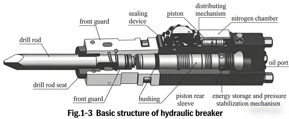
(1) தாக்க இயந்திரம்
ஒரு இயற்கை திரவ பாறை உடைப்பி (ஹைட்ராலிக் ராக் பிரேக்கர்) ஒப்பீட்டளவில் நீளமானதும், மெல்லியதுமான பிஸ்டனைக் கொண்டிருக்கிறது, இது மிக முக்கியமான பாகமாகும். வலுவூட்டல் அலை கடத்தல் கோட்பாட்டின் அடிப்படையில், பிஸ்டனின் தாக்க ஆற்றலை அதிகபட்சமாகக் கடத்துவதற்கு, தாக்க பிஸ்டனின் விட்டம் பொதுவாக சிசல் வாலின் முனை விட்டத்திற்கு ஏறக்குறைய சமமாகவோ அல்லது அதற்கு அருகிலேயே இருக்கும்; இது தாக்கும் முகப்பில் முழுமையான தொடர்பை உறுதிப்படுத்தி, ஆற்றலை திறம்பட கடத்துவதற்கான நோக்கத்தை அடைகிறது. தாக்க பிஸ்டனுக்கும் சிலிண்டர் உடலுக்கும் (அல்லது லைனர் சீவ்) இடையேயான பொருத்து இடைவெளி என்பது மிக முக்கியமான தொழில்நுட்ப அளவுருவாகும். இந்த இடைவெளி மிகையாக இருந்தால், மிகப்பெரிய உள் கசிவு ஏற்படும், இதனால் தாக்க விசை போதுமானதாக இருக்காது, மேலும் பாறை உடைப்பி சாதாரணமாகச் செயல்படாமல் போகலாம்; இந்த இடைவெளி மிகக் குறைவாக இருந்தால், பிஸ்டனின் இயக்கம் மெதுவாக இருக்கலாம் அல்லது காலிங் (galling) ஏற்படலாம், அதே நேரத்தில் தயாரிப்பு செலவுகள் கணிசமாக அதிகரிக்கும்.
(2) பகிர்வு வினைமுறை
ஒரு இயற்கை எண் உடைப்பான் (ஹைட்ராலிக் ராக் பிரேக்கர்) பொதுவாக ஹைட்ராலிக் எண்ணெய் ஓட்டத்தின் திசையை மாற்றும் ஒரு பரவல் வால்வைக் கொண்டுள்ளது, அதன் மூலம் தாக்க முள்ளின் (இம்பாக்ட் பிஸ்டன்) முன்னும் பின்னும் நகரும் இயக்கத்தை கட்டுப்படுத்தி இயக்குகிறது. பரவல் வால்வின் கட்டமைப்பு வடிவங்கள் பலவாகும்; அவை பொதுவாக இரண்டு முக்கிய வகைகளாகப் பிரிக்கப்படுகின்றன: ஸ்பூல் வால்வுகள் (spool valves) மற்றும் ஸ்லீவ் வால்வுகள் (sleeve valves). ஸ்பூல் வால்வுகள் பொதுவாக எடை குறைவாகவும், எண்ணெய் நுகர்வு குறைவாகவும், விட்டம் சிறியதாகவும், இணைந்த இடைவெளி (mating clearance) மற்றும் கசிவு குறைவாகவும் இருக்கும்; ஆனால் அவை பெரும்பாலும் படிநிலை வடிவமைப்பை (step-shaped structure) கொண்டவையாகவும், கட்டமைப்பு செயலாக்கத்திற்கு (structural machinability) ஒப்பீட்டளவில் மோசமாகவும், தடுப்பு இழப்புகள் (throttling losses) அதிகமாகவும் இருக்கும். ஸ்லீவ் வால்வுகள் எடை அதிகமாகவும், விட்டம் பெரியதாகவும், இணைந்த இடைவெளி மற்றும் கசிவு ஒப்பீட்டளவில் அதிகமாகவும் இருக்கும்; ஆனால் அவற்றின் கட்டமைப்பு செயலாக்கத்திற்கு ஏற்றதாகவும், திறப்பு பரப்பு சாய்வு (opening area gradient) அதிகமாகவும், தடுப்பு இழப்புகள் குறைவாகவும் இருக்கும். வால்வு ஸ்பூல் மற்றும் வால்வு உடல் அல்லது வால்வு ஸ்லீவ் இடையேயான இணைந்த இடைவெளி என்பது ஹைட்ராலிக் ராக் பிரேக்கர் தயாரிப்பில் மற்றொரு முக்கிய தொழில்நுட்ப அளவுருவாகும்; இந்த இடைவெளி மிகையாகவோ அல்லது குறைவாகவோ இருந்தால், வால்வு சரியாக இயங்க முடியாது.
(3) சேமிப்புத் தொட்டி அழுத்த-நிலைத்தன்மை ஏற்பாடு
பெரும்பாலான ஹைட்ராலிக் பாறை உடைப்பிகளில் ஒன்று அல்லது அதற்கு மேற்பட்ட சேமிப்புத் தொட்டிகள் (அக்கியூமுலேட்டர்கள்) இருக்கும், அவை ஆற்றலைச் சேமித்தல் மற்றும் அழுத்தத்தை நிலைநிறுத்துதல் ஆகிய பணிகளைச் செய்கின்றன. ஹைட்ராலிக் பாறை உடைப்பி வெளிப்புறத்தில் வேலை செய்வது முக்கிய ஓட்ட நிலையின் போது மட்டுமே; திரும்பும் ஓட்ட நிலை என்பது முக்கிய ஓட்ட நிலைக்கான தயாரிப்பு நிலையாகும். பிஸ்டன் திரும்பும்போது, ஹைட்ராலிக் எண்ணெய் சேமிப்புத் தொட்டியில் நிரப்பும் அறையின் அழுத்தத்தை விட அதிக அழுத்தத்தில் நுழைந்து, அத்தொட்டியில் எண்ணெயின் நிலை ஆற்றலாகச் சேமிக்கப்படுகிறது. இந்த ஆற்றல் பிஸ்டனின் முக்கிய ஓட்ட நிலையின் போது வெளியிடப்படுகிறது, மேலும் திரும்பும் ஓட்ட நிலையின் ஆற்றலின் பெரும்பகுதியை தாக்க ஆற்றலாக மாற்றுகிறது. இவ்வாறு, சேமிப்புத் தொட்டி அமைப்பின் செயல்திறனை மேம்படுத்தும் பங்களிப்பைச் செய்கிறது, மேலும் பரிசோதனை வால்வின் ஸ்பூல் மாற்றத்தால் ஏற்படும் அழுத்த அதிர்ச்சிகள் மற்றும் ஓட்ட அலைவுகளைக் குறைக்கிறது.
(4) இயக்கும் ஏற்பாடு
சிசல் என்பது ஹைட்ராலிக் ராக் பிரேக்கரின் செயல்படுத்தும் பகுதியாகும், இது வெளிப்புற வேலையைச் செய்கிறது மற்றும் பணிப்பொருளில் நேரடியாகச் செயல்படுகிறது; இது தரமான அரிப்பு எதிர்ப்புத் தன்மையைக் கொண்ட தேய்மானப் பகுதியாகும், வெளிப்புறம் கடினமாகவும், உள்புறம் வலுவாகவும் இருக்க வேண்டும், மேலும் வெளிப்புறத்திலிருந்து உள்புறம் நோக்கி கடினத்தன்மை படிப்படியாக மாறும் வகையில் இருக்க வேண்டும். பல்வேறு பணிச் சூழல்கள் மற்றும் பணிப் பொருள்களுக்கு ஏற்றவாறு பயன்படுத்த, சிசல்கள் கூர்மையான, சதுர, பூமிக்கோட்டை (ஸ்பேட்) மற்றும் தட்டைத் தலை வடிவங்களில் கிடைக்கின்றன.
(5) காலியாக சுடுதலைத் தடுக்கும் இயந்திர அமைப்பு
ஒரு ஹைட்ராலிக் ராக் பிரேக்கர் அதிக தாக்க ஆற்றலைக் கொண்டிருப்பதால், பிஸ்டனை உள்ளே நேரடியாக சிலிண்டர் உடலைத் தாக்கச் செய்ய அனுமதித்தால், அது ராக் பிரேக்கர் உடலை மிகவும் கடுமையாகச் சேதப்படுத்தும் — இது 'பிளாங்க்-ஃபைரிங்' (காலியாக வெடித்தல்) எனப்படும். பிளாங்க்-ஃபைரிங் தடுப்பு அமைப்பு என்பது சிலிண்டர் உடலின் முன்புறத்தில் ஒரு ஹைட்ராலிக் பஃபர் அறையைச் சேர்ப்பதைக் குறிக்கிறது. சிசல் (chisel) பாறையைத் தொடாமல் முன்னோக்கி நகரும்போது, தாக்க பிஸ்டன் பஃபர் அறைக்குள் நுழைந்து, அதிலுள்ள எண்ணெயைச் சுருக்கி, தாக்க ஆற்றலை உறிஞ்சி, இயந்திரத்தின் உடலுக்கு மென்மையான பாதுகாப்பை வழங்குகிறது. அதே நேரத்தில், முன்புற அறையின் எண்ணெய் உள்ளீட்டு துளை மூடப்படுகிறது, எனவே ஈர்ப்பு விசை மற்றும் பின்புறத்தில் உள்ள நைட்ரஜனின் செயல்பாட்டால் பிஸ்டன் பின்னோக்கி நகர முடியாது; சிசல் மீண்டும் பாறையைத் தொட்டு, கையின் அழுத்தத்தால் பின்னோக்கி தள்ளப்படும்போது மட்டுமே, தாக்க பிஸ்டன் பஃபர் அறையிலிருந்து வெளியேறி, உயர் அழுத்த எண்ணெய் முன்புற அறைக்குள் நுழைந்து, சாதாரண இயக்கம் தொடர முடியும். படம் 1-4 இல் காட்டப்பட்டுள்ளது போல, ஹைட்ராலிக் ராக் பிரேக்கர் உடைக்க வேண்டிய பொருளை முற்றிலும் உடைத்த பின்னர், பிஸ்டன் அதிகபட்சம் 1 முதல் 2 முறை வரை பிளாங்க்-ஃபைரிங் செய்து நின்றுவிடும். இயக்குநர் மீண்டும் தாக்க புள்ளியைத் தேர்ந்தெடுத்து, சிசலை நன்றாக அழுத்தி, அழுத்தத்தைச் செலுத்த வேண்டும்; அப்போது சிசல் பிஸ்டனை கீழ் அறையின் எண்ணெய் உள்ளீட்டு துளையிலிருந்து விலக்கி, பணி மீண்டும் தொடங்க முடியும். 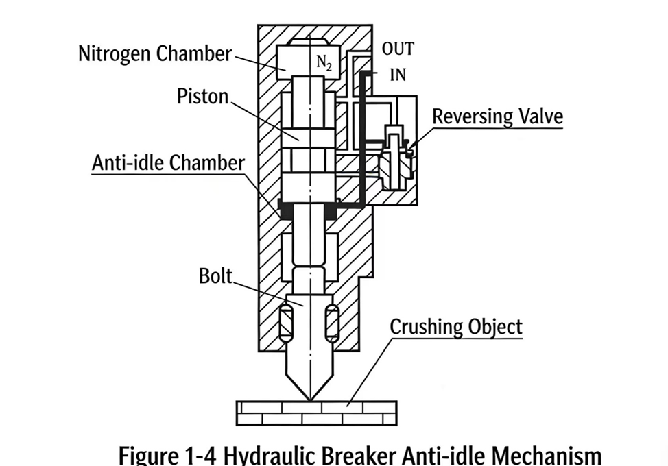
(6) மற்ற வழிமுறைகள்
ஹைட்ராலிக் ராக் பிரேக்கரின் மற்ற வழிமுறைகளில் இவை அடங்கும்: இணைப்பு சட்டம், அதிர்வு குறைப்பு வழிமுறை, சீலிங் அமைப்பு, தானியங்கி எண்ணெயிடும் அமைப்பு மற்றும் பிற.
ஹைட்ராலிக் ராக் பிரேக்கர்கள் பல வகைகளில் உள்ளன மற்றும் பல வகைப்பாட்டு முறைகள் உள்ளன. முக்கிய வகைப்பாட்டு முறைகள் பின்வருமாறு:
(1) இயக்க முறை வாரியாக வகைப்பாடு
ஹைட்ராலிக் ராக் பிரேக்கர்கள் இயக்க முறை வாரியாக, கேரியர்-மவுண்டெட் (வாகனத்தில் பொருத்தப்பட்ட) மற்றும் கையால் பிடிக்கும் வகை என இருவகையாக வகைப்படுத்தப்படுகின்றன. கையால் பிடிக்கும் வகைகள் சிறிய ராக் பிரேக்கர்கள் ஆகும், இவை ஹைட்ராலிக் சிசல்கள் எனவும் அழைக்கப்படுகின்றன; இவற்றின் நிறை பொதுவாக 30 கிலோகிராமுக்கு கீழேயே இருக்கும், கையால் இயக்கப்படும், தனிப்பயன் ஹைட்ராலிக் பம்ப் நிலையத்தால் இயக்கப்படும் மற்றும் காற்றழுத்த சிசல் இயக்கங்களை பரவலாக மாற்றிட முடியும். கேரியர்-மவுண்டெட் வகைகள் நடுத்தர மற்றும் பெரிய ராக் பிரேக்கர்கள் ஆகும், இவை நேரடியாக ஹைட்ராலிக் எக்ஸ்கவேட்டர்கள், லோடர்கள் மற்றும் பிற ஹைட்ராலிக் கேரியர் இயந்திரங்களின் பூமின் மீது பொருத்தப்படுகின்றன, மேலும் கேரியர் இயந்திரத்தின் சக்தி அமைப்பு, ஹைட்ராலிக் அமைப்பு மற்றும் பூம் இயக்க அமைப்பு ஆகியவற்றைப் பயன்படுத்தி இயக்கங்களை மேற்கொள்ளும்.
(2) செயல்பாட்டு ஊடகத்தின் அடிப்படையில் வகைப்பாடு
ஹைட்ராலிக் பாறை உடைப்பிகள், செயல்பாட்டு ஊடகத்தின் அடிப்படையில், முழுமையாக ஹைட்ராலிக், ஹைட்ராலிக்-பனிமம் கலவை, மற்றும் நைட்ரஜன்-வெடிப்பு என மூன்று முக்கிய வகைகளாக வகைப்படுத்தப்படுகின்றன. முழுமையாக ஹைட்ராலிக் வகைகள் பிஸ்டனைச் செயல்படுத்த முற்றிலும் ஹைட்ராலிக் எண்ணெய் அழுத்தத்தை நம்பியுள்ளன; ஹைட்ராலிக்-பனிமம் கலவை வகைகள் பிஸ்டனைச் செயல்படுத்த ஹைட்ராலிக் எண்ணெய் மற்றும் பின்புறத்தில் உள்ள செறிவூட்டப்பட்ட நைட்ரஜன் ஆகிய இரண்டையும் ஒரே நேரத்தில் பயன்படுத்துகின்றன; நைட்ரஜன்-வெடிப்பு வகைகள் பின்புற நைட்ரஜன் அறையில் உள்ள நைட்ரஜனின் கணநேர விரிவாக்கத்தை முற்றிலும் நம்பியுள்ளன, அது பிஸ்டனை வேலை செய்ய தள்ளுகிறது.
(3) பின்னூட்ட முறையின் அடிப்படையில் வகைப்பாடு
ஹைட்ராலிக் ராக் பிரேக்கர்கள் பின்னூட்ட முறையின் அடிப்படையில் ஸ்ட்ரோக் பின்னூட்டம் மற்றும் அழுத்த பின்னூட்டம் என வகைப்படுத்தப்படுகின்றன. இவற்றின் வேறுபாடு, விநியோக வால்வ் மாற்றத்திற்கான பின்னூட்ட சிக்னலை எவ்வாறு சேகரிக்கின்றன என்பதில் உள்ளது. ஸ்ட்ரோக் பின்னூட்ட ஹைட்ராலிக் ராக் பிரேக்கர்கள், பிஸ்டன் ஸ்ட்ரோக்கின் போது உயர் அழுத்த எண்ணெய் பின்னூட்ட துளைகளைத் திறக்கவும் மூடவும் சார்ந்துள்ளன; இந்த பின்னூட்ட துளைகளின் இடங்களை வலுவாக நிர்ணயிக்க முடியும் மட்டுமே, மேலும் கட்டமைப்பு நிலைமைகளால் வரையறுக்கப்பட்டு, அதிகபட்சம் 3 பின்னூட்ட துளைகளை மட்டுமே அமைக்க முடியும்; எனவே, ஸ்ட்ரோக் பின்னூட்ட ஹைட்ராலிக் ராக் பிரேக்கர்கள் தாக்க அதிர்வெண்ணின் தடையில்லா சரிசெய்வை (ஸ்டெப்லெஸ் அட்ஜஸ்ட்மென்ட்) அடைய முடியாது. அழுத்த பின்னூட்ட ஹைட்ராலிக் ராக் பிரேக்கர்கள், பிஸ்டன் வாலின் முனையில் அமைந்துள்ள அமைப்பு அழுத்தத்தையோ அல்லது நைட்ரஜன் அறை அழுத்தத்தையோ சேகரித்து விநியோக வால்வ் மாற்றத்தைக் கட்டுப்படுத்துகின்றன; பிஸ்டன் நைட்ரஜன் அறைக்குள் நுழையும்போது, நைட்ரஜன் அறை அழுத்தம் தொடர்ந்து மாறுகிறது, மேலும் அந்த அறையில் பொருத்தப்பட்டுள்ள அழுத்த சென்சார் ஒரு முன்கண்ட அழுத்தத்தைக் கண்டறிந்தவுடன், நுண்கணினி கட்டுப்பாட்டின் மூலம் வால்வ் மாற்றம் ஏற்படுகிறது; மாற்ற அழுத்தத்தை ஏதேனும் மதிப்பாக அமைக்க முடிவதால், அழுத்த பின்னூட்ட ஹைட்ராலிக் ராக் பிரேக்கர்கள் தாக்க அதிர்வெண்ணின் தடையில்லா சரிசெய்வை அடைய முடியும்.
(4) விநியோக முறையின் அடிப்படையில் வகைப்பாடு
விநியோக வால்வின் வடிவத்தை அடிப்படையாகக் கொண்டு, இவை முக்கட்டளை வால்வு ஒற்றை-முக எண்ணெய் திருப்பியனுப்பு மற்றும் நான்கு-கட்டளை வால்வு இரட்டை-முக எண்ணெய் திருப்பியனுப்பு என இரண்டு பெரும் வகைகளாக வகைப்படுத்தப்படுகின்றன. ஒற்றை-முக எண்ணெய் திருப்பியனுப்பு கட்டமைப்பு வடிவங்களுக்கு எளிய எண்ணெய் கடத்தும் பாதைகள் மற்றும் எளிதில் கட்டுப்படுத்தக்கூடிய பண்புகள் உள்ளன; நடைமுறையில், இவை ஒப்பீட்டளவில் பொதுவாகப் பயன்படுத்தப்படுகின்றன. ஒற்றை-முக எண்ணெய் திருப்பியனுப்பு முன்-அறை எண்ணெய் திருப்பியனுப்பு மற்றும் பின்-அறை எண்ணெய் திருப்பியனுப்பு என இரண்டு வகைகளாகப் பிரிக்கப்படுகின்றன; இவற்றில், முன்-அறை எண்ணெய் திருப்பியனுப்பு வடிவங்களுக்கு அதிக உறிஞ்சுதல் மற்றும் எண்ணெய் திருப்பியனுப்பு எதிர்ப்பு ஆகிய குறைபாடுகள் உள்ளன, எனவே தற்போது மிகவும் பொதுவாகக் காணப்படும் வடிவம் முன்-அறை மாறா அழுத்தம், பின்-அறை எண்ணெய் திருப்பியனுப்பு வடிவமாகும். நான்கு-கட்டளை வால்வு இரட்டை-முக எண்ணெய் திருப்பியனுப்பு இரட்டை-செயல்பாட்டு வகை எனவும் அழைக்கப்படுகிறது; இதன் தன்மை என்பது மாறா அழுத்த அறை இல்லாமையும், முன் மற்றும் பின் அறைகளின் அழுத்தங்கள் மாறி மாறி அதிகமாகவும் குறைவாகவும் இருத்தலுமாகும்; ஆனால், இரட்டை-முக எண்ணெய் திருப்பியனுப்பு கட்டமைப்பு வடிவத்தின் சிக்கலான எண்ணெய் கடத்தும் பாதைகள் காரணமாக, இது அரிதாகவே பயன்படுத்தப்படுகிறது.
(5) பரிசோதனை வால்வு அமைப்பு வாரியாக வகைப்பாடு
பரிசோதனை வால்வு அமைப்பு அடிப்படையில், இவை உள்-மவுண்ட் (internal-mount) மற்றும் வெளி-மவுண்ட் (external-mount) என இரு வகைகளாக வகைப்படுத்தப்படுகின்றன. உள்-மவுண்ட் வகை மேலும் ஸ்பூல் வகை (spool type) மற்றும் ஸ்லீவ் வகை (sleeve type) என இரு வகைகளாக வகைப்படுத்தப்படுகிறது. உள்-மவுண்ட் பரிசோதனை வால்வுகள் சிலிண்டர் உடலுடன் ஒன்றிணைந்து குறுகிய அமைப்பில் வடிவமைக்கப்படுகின்றன; வெளி-மவுண்ட் பரிசோதனை வால்வுகள் சிலிண்டர் உடலுக்கு வெளியே தனித்தனியாக அமைந்துள்ளன, இவை எளிய அமைப்பைக் கொண்டுள்ளன மற்றும் பராமரிப்பு மற்றும் மாற்றுதல் எளிதாகும்.
மேலும், ஒலிமட்டத்தின் அடிப்படையில் இவை குறைந்த-ஒலிமட்ட (low-noise) மற்றும் தரநிலை (standard) வகைகளாக வகைப்படுத்தப்படுகின்றன; வெளிப்புற கவர் வடிவத்தின் அடிப்படையில் முக்கோண வடிவ, கோபுர வடிவ மற்றும் மூடிய பாறை உடைப்பான்கள் (enclosed rock breakers) போன்றவையாக வகைப்படுத்தப்படுகின்றன. இவ்வகை வகைப்பாடுகள் அனைத்தும் படம் 1-5இல் சுருக்கமாகக் கொடுக்கப்பட்டுள்ளன. 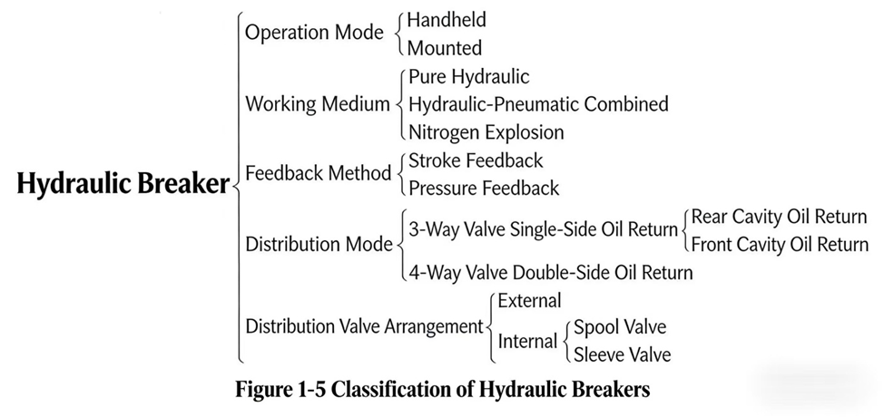

HOVOO-வை வரவேற்க, ஒரு சீன அடிமை உற்பத்தி அலுவலகம். PU, Rubber மற்றும் PTFE அடிமைகளை உற்பத்துகிறது. அடிமைகள் O-ring, piston seal, rod seal, Gray ring மற்றும் gas seal ஐ உள்ளடக்கியவை.


 EN
EN
 AR
AR CS
CS DA
DA NL
NL FI
FI FR
FR DE
DE EL
EL IT
IT JA
JA KO
KO NO
NO PL
PL PT
PT RO
RO RU
RU ES
ES SV
SV TL
TL IW
IW ID
ID LV
LV SR
SR SK
SK VI
VI HU
HU MT
MT TH
TH TR
TR FA
FA MS
MS GA
GA CY
CY IS
IS KA
KA UR
UR LA
LA TA
TA MY
MY