33-99No. Mufu E Rd. Gulou District, Nanjing, China [email protected] | [email protected]
33-99No. Mufu E Rd. Gulou District, Nanjing, China [email protected] | [email protected]

The first type of directional valve to consider is one with four internal passages: a pressure passage, a return (tank) passage, and two work passages. This is the four-way directional valve — named for the four different passages in its valve body. The four-way directional valve controls hydraulic cylinders or hydraulic motors to reverse direction.
All directional valves consist of a valve body and internal moving spool. The spool has at least two positions — two end positions. These two positions are shown in a directional valve graphic symbol by two separate boxes. In each box, arrows are used to show how the valve body internal passages are connected when the spool is at that position. When showing a directional valve with a graphic symbol, both boxes must be connected together. When placing it in a circuit, exactly one box must connect in the circuit. By doing this, when the actuator moves in one direction, the internal flow path in the directional valve is clearly shown. When the symbol's other box needs to show the actuator moving in the opposite direction, simply slide the other box smoothly into the circuit.
A directional valve with only two spool positions is called a two-position valve.
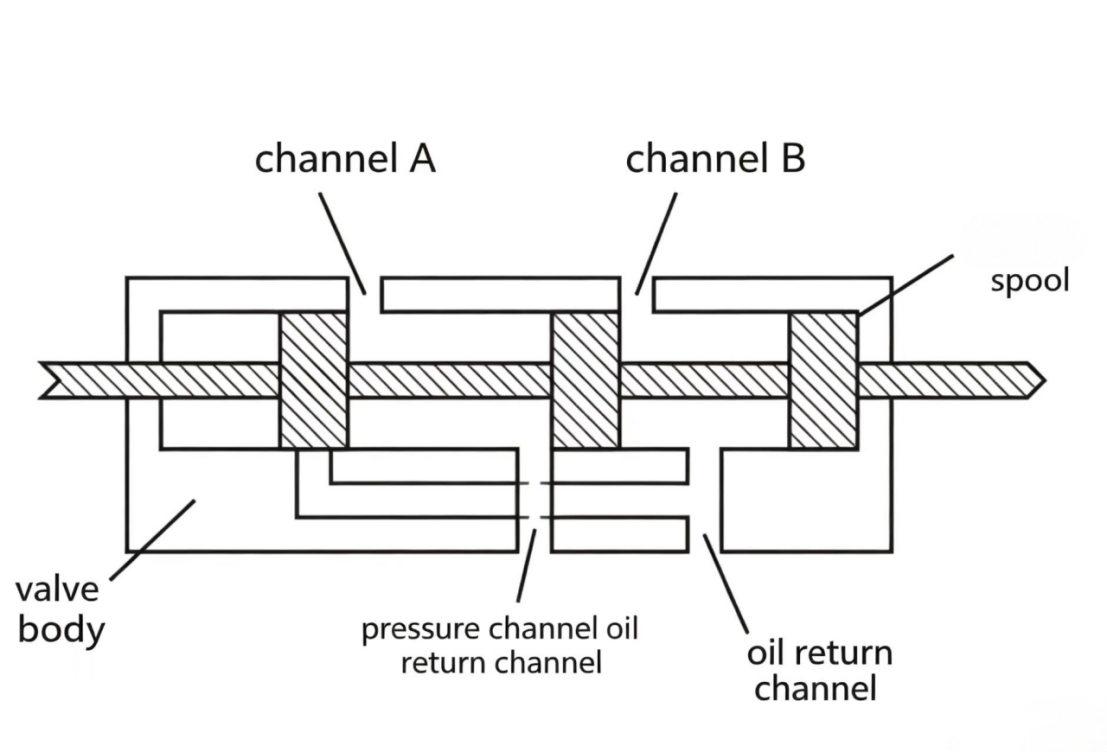
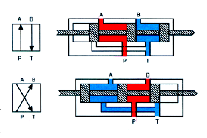
Figure 10-1 Four-way directional valve. The two-box symbol represents the two spool positions. Only one box connects into the circuit at a time; shifting the spool swaps which box is active, reversing the cylinder.
When the spool is at one end position, the pressure passage connects to work passage A, and the return passage connects to work passage B. When the spool switches to the other end position, the pressure passage connects to work passage B, and the return passage connects to work passage A. Switching the spool's end position switches the direction of oil flow into the hydraulic cylinder, extending or retracting the rod.
A three-way directional valve has three internal passages: a pressure passage, a return passage, and one work passage. Its function is: when the spool is at one end position, it pressurizes the work port; when at the other end position, it depressurizes the work port. In other words, the three-way valve switches pressurizing and depressurizing of a single work port.
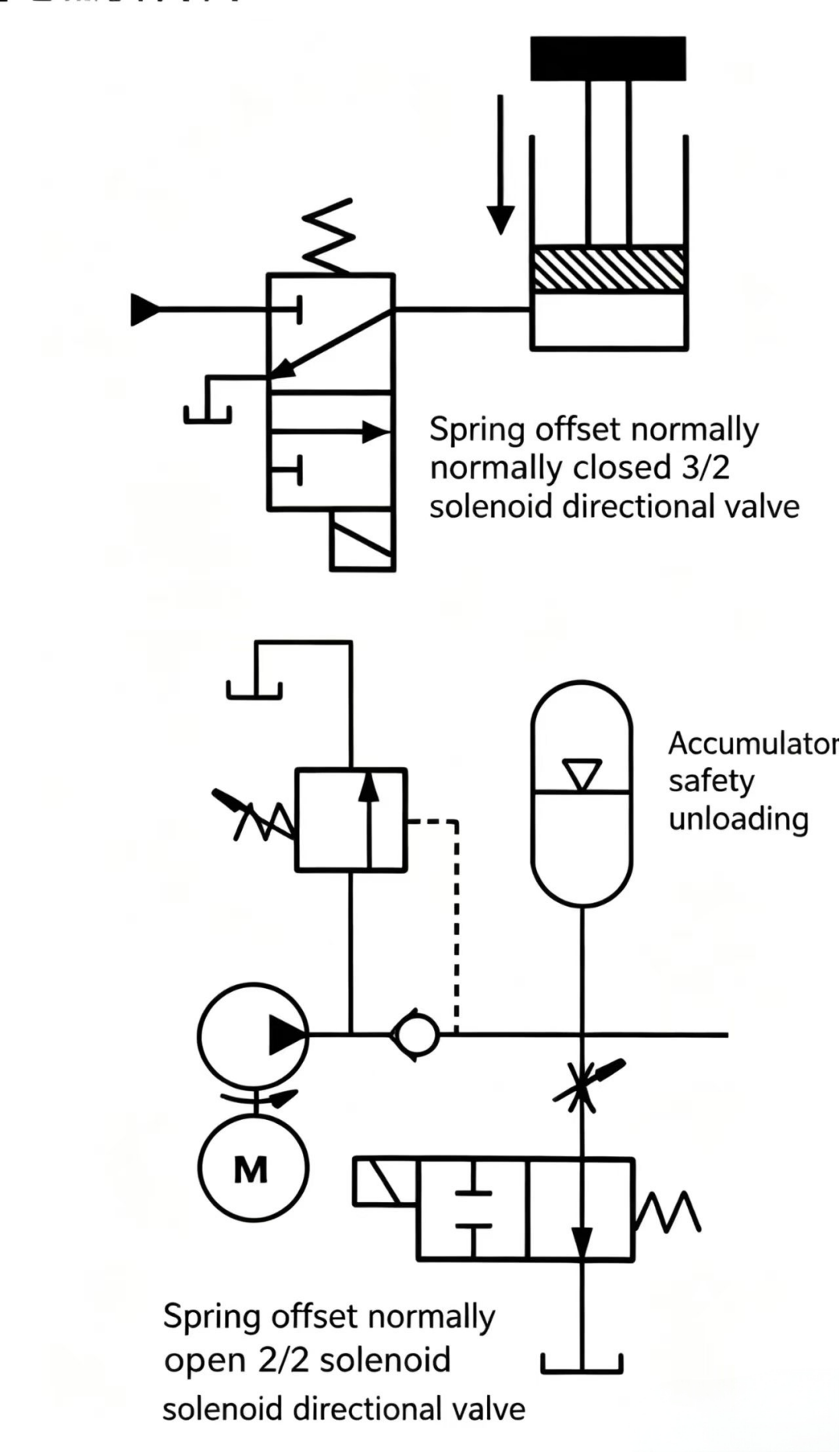
A three-way valve can control single-acting actuators such as spring-return plunger cylinders. In such applications, the three-way valve in one position feeds pressure oil into the cylinder rod-free end; when switched to the other position, the flow into the actuator is blocked, and the actuator passage connects to the return passage inside the valve body, so the cylinder rod can retract by gravity or spring force.
When the three-way valve is at the position connecting the work passage to the return passage, a vertically mounted plunger cylinder can retract under gravity, while a spring-return cylinder rod retracts under spring force.
In industrial hydraulic applications, three-way valves are rarely found. If a three-way function is needed, a four-way valve with one work port blocked is usually substituted.
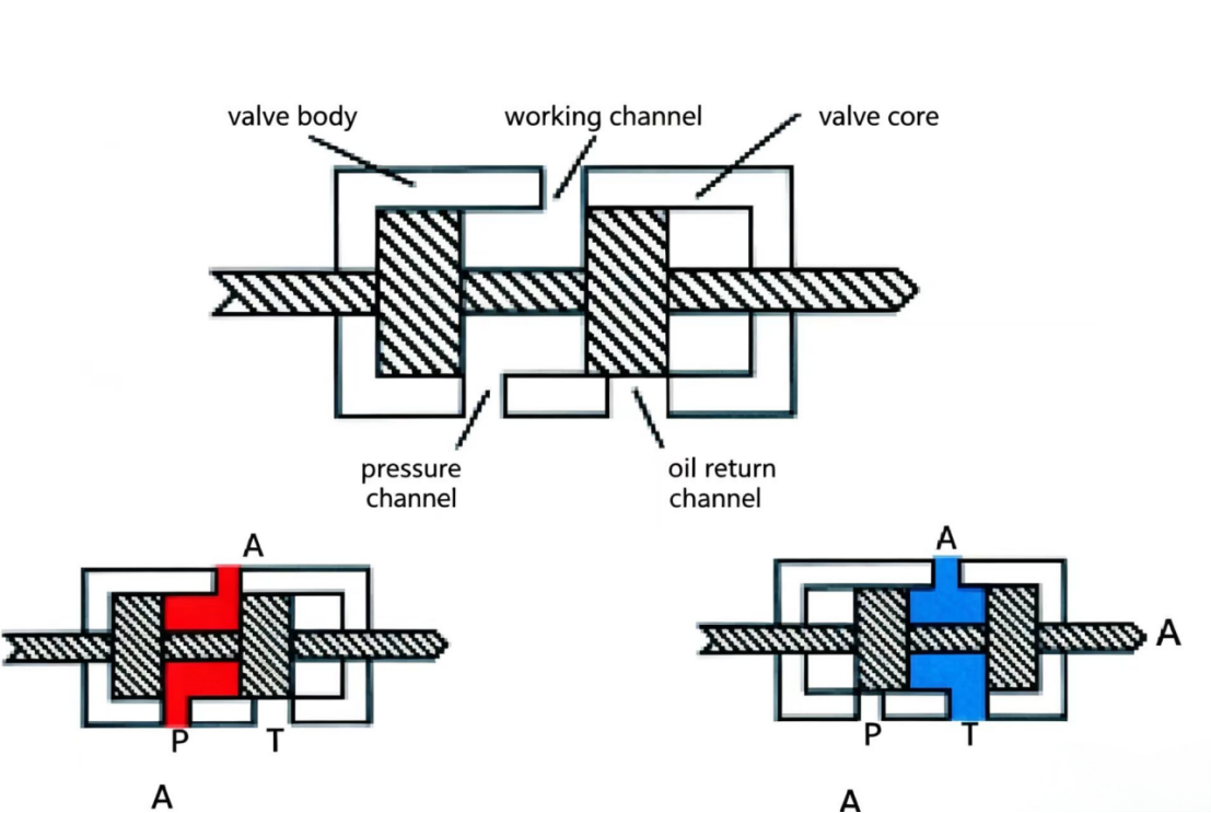
Figure 10-3 Three-way directional valve controls single-acting (spring-return) cylinders. One position pressurizes; the other connects the cylinder to tank and lets the spring retract the rod.
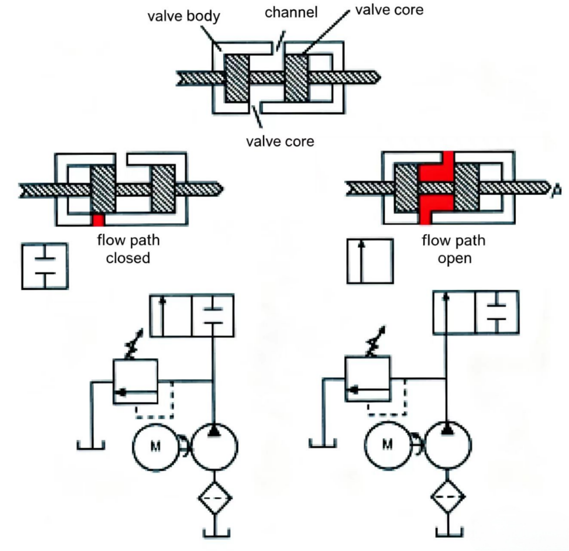
A two-way directional valve has only two passages — these two passages can be connected or disconnected by the spool. When the spool is at one end position, the flow passage through the valve is open; when at the other end position, the passage is closed.
The two-way directional valve acts as an on/off switch in a circuit. This function is used in many systems as a safety interlock, or to isolate and connect various components within the system.
Directional control valves used in industrial hydraulics come in several basic sizes: 1/4", 3/8", 1/2", 3/4", and 1-1/4" (6.35 mm, 9.5 mm, 12.7 mm, 19.05 mm, and 31.75 mm). In industrial applications they are commonly rated by their average flow capacity rather than by port size. For example, rated capacities are: 3–10 gpm (11.37–37.9 lpm), 10–20 gpm (37.9–45.48 lpm), 40 gpm (75.8 lpm), 80 gpm (303.2 lpm), and 160 gpm (379 lpm). At the rated flow, the pressure drop from P to A or B to T is approximately 40 psi (2.76 bar).
The four-way directional valve spool we have seen is a shaft with three large-diameter cylindrical sections called lands. The equal spacing between the three lands defines this as a three-land spool. Most industrial hydraulic directional valves are two-land or four-land spools. Lower-rated flow valves typically use two-land spools; four-land spools are more common in larger flow-rated valves.
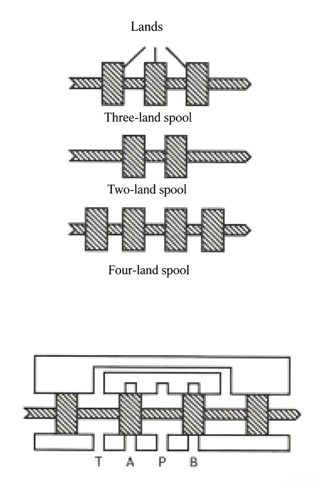
Figure 10-5 Directional valve spools. Two-land spools are common in smaller valves; four-land spools in larger ones. The number and position of lands determines which passages are connected or blocked in each spool position.
The four-way directional valve described above has four ports. Usually, the pressure and return ports are on one side of the valve body, while the two work ports are on the opposite side. This port arrangement is very close to the directional valve graphic symbol. For ease of installation, most industrial hydraulic directional valves use subplate-mounted design: the valve body is bolted to a subplate that connects to the system lines. The subplate-mounted valve ports are on the bottom face of the valve body.
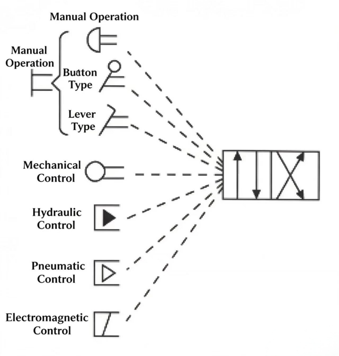
We have seen that the directional valve spool can be positioned at one end or the other. Moving the spool can be done by mechanical, electrical, hydraulic, pneumatic, or manual means.
A directional valve moved by muscle power is called a hand-operated valve. There are many types of manual operating devices, including levers, push-buttons, and foot pedals. The most common mechanical operating mechanism is a cam pin whose top is fitted with a roller — when the cam on the actuator moves down and hits the roller, the spool shifts to another position. With manual operation, the directional valve action sequence and control must be determined by the operator's intention. If the directional valve must shift at a specific actuator position, a mechanically operated directional valve can be used.
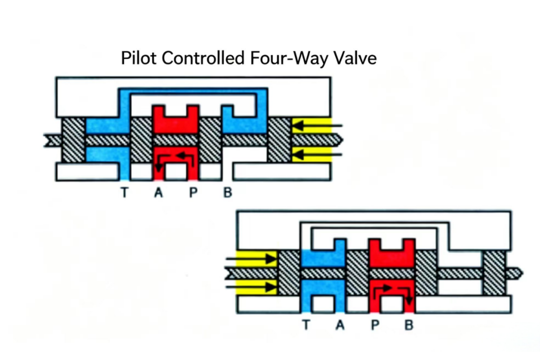
Directional valve spools can also be shifted using pneumatic or hydraulic pilot pressure. For four-land spools, pilot pressure acts on the spool lands at both end positions. For two-land spools, pilot pressure acts on a single pilot piston.
The most common way to control a directional valve is with a solenoid (electromagnet). A solenoid is an electromechanical device that converts electrical energy into linear mechanical force and motion. The corresponding actuator in a hydraulic system is the hydraulic cylinder.
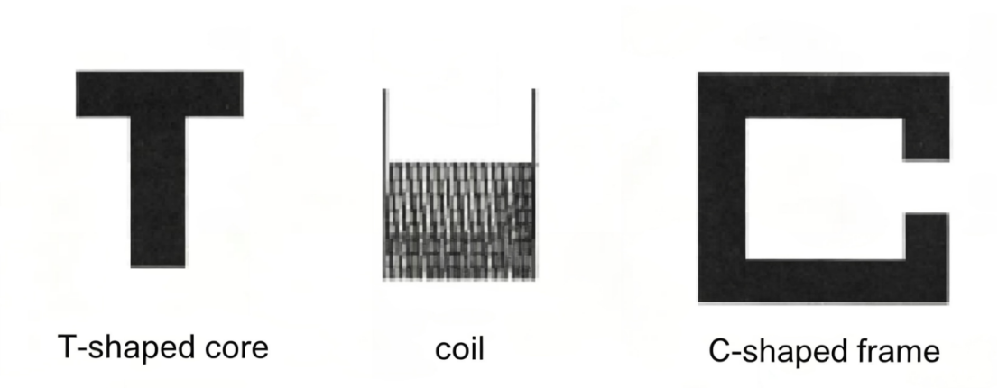
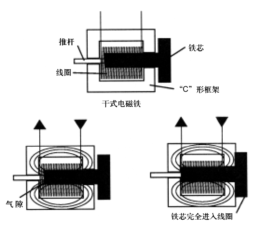
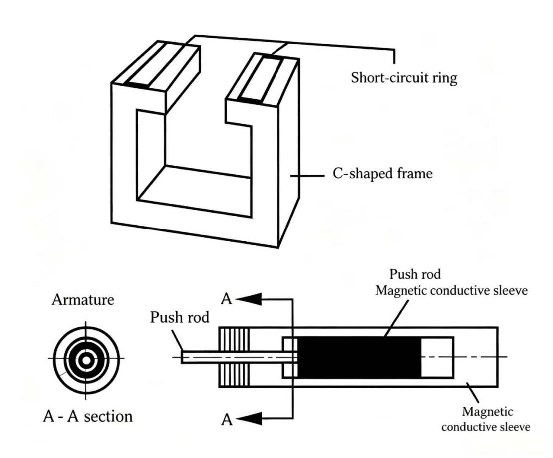
Of the two solenoid types, the dry-type is the earlier design. It works on basic electromagnetic principles and consists of a "T"-shaped iron core, a coil, and a "C"-shaped frame. Because of the shape of the iron core and the frame surrounding the coil, this type is sometimes called a "CT" electromagnet. Iron is a good magnetic conductor while air has poor magnetic conductivity. The dry-type solenoid operating principle is: the magnetic field pulls the iron core into the coil, reducing the large magnetic resistance caused by the air gap at the coil center. As the iron core moves in, the air gap gradually decreases, the electromagnetic push force increases, and the electromagnetic force when the iron core is inside the coil is greater than when it is outside.
The wet-type solenoid is a relatively newer design in the industrial hydraulics field. Compared to air-gap designs, the wet solenoid's advantage is better heat dissipation and the elimination of push-rod seals that can cause leaks in dry-type solenoids, improving reliability.
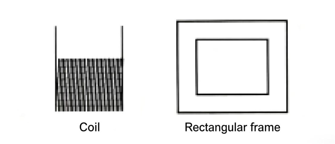
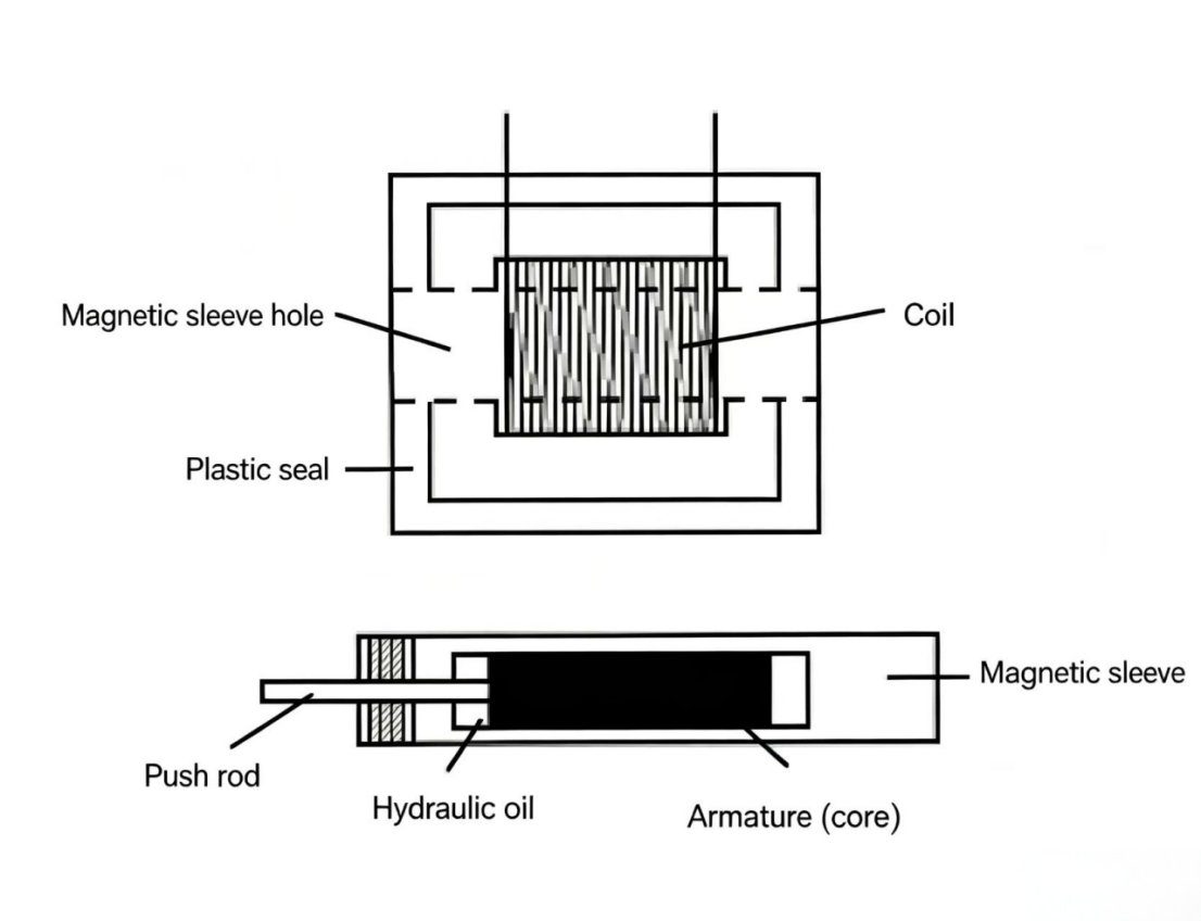
A wet-type solenoid consists of a coil, rectangular frame, push rod, armature (iron core), and a guide tube. The coil is enclosed in the rectangular frame; both are sealed together with plastic. This assembly has a through-hole running through the coil center and both sides of the frame — this hole fits over the guide tube. The guide tube contains the armature. The guide tube is press-fitted onto the directional valve body; the guide tube internal cavity connects to the directional valve return passage, so the armature is immersed in system oil — this is why it is called a "wet armature."
When current flows through the coil, the coil generates a magnetic field, strengthened by the rectangular iron magnetic path around the coil and the armature at the coil center. When current is applied to the wet armature coil, the movable armature is partially outside the coil. The current-produced magnetic field pulls the armature in, hitting the push rod mechanically connected to the valve spool, shifting the directional valve. As the spool shifts, the armature fully enters the coil, concentrating the coil magnetic field completely in the iron magnetic path.
Iron is a good magnetic conductor, while the oil surrounding the armature and push rod has very poor magnetic conductivity. The wet-type solenoid operating principle is: the magnetic field pulls the armature in to reduce the large air gap at the coil center. As the armature moves in, the gap gradually decreases, electromagnetic push force increases, and when the armature is fully inside the coil the electromagnetic force is greater than outside.
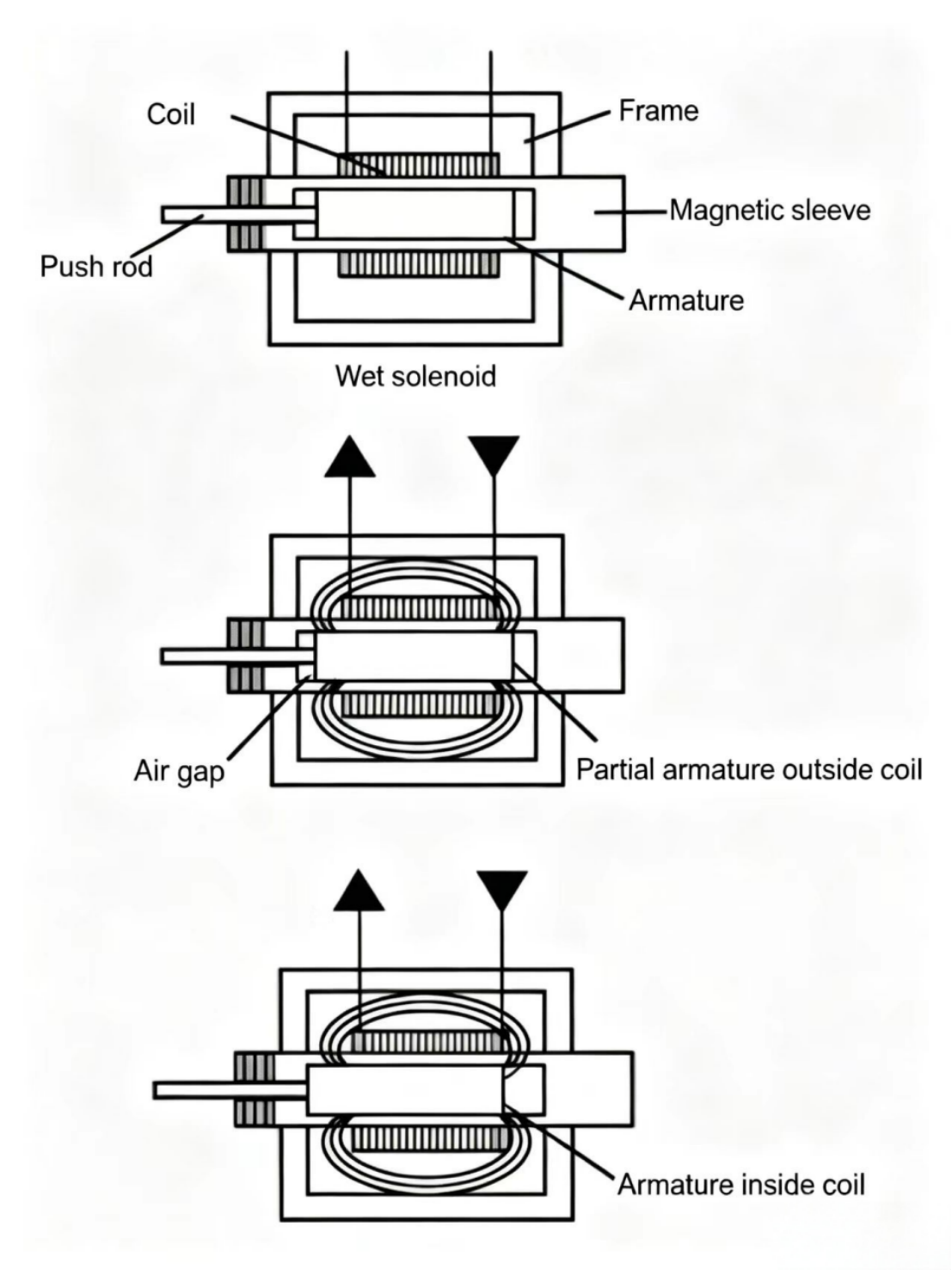
Figure 10-9 Wet-type solenoid. The armature is immersed in hydraulic oil (hence "wet"), eliminating the push-rod dynamic seal. Better heat dissipation and reliability compared to dry-type.
In the United States, industrial control power is typically AC. US AC current cycles from zero to positive peak, back through zero to negative peak, and back to zero at 60 cycles per second (60 Hz). When current is at positive or negative peak, the magnetic field and electromagnetic force are maximum. As current decreases through zero, the magnetic field and force also decrease, causing the spring-biased solenoid load (normally the spring-biased valve spool) to push the iron core or armature out. When the field and force build again, they pull the iron core or armature back in. This motion creates the solenoid's buzzing, humming, or vibration sound — AC hum.
To reduce AC hum and increase solenoid push force, a short-circuit ring (shading coil) is used for compensation. In dry-type solenoids, the short-circuit ring is a copper ring attached to the C-shaped frame. In wet-type solenoids, it is a copper ring at the push-rod end of the guide tube. When the solenoid operates, the ring induces a current that lags behind the applied working current. This way, when the main magnetic field of the coil is at its minimum, the short-circuit ring magnetic field is sufficient to hold the iron core or armature, greatly reducing AC hum.
The pulsating AC magnetic field can create small stray currents in the solenoid — these are eddy currents, which flow in small circuits in the iron magnetic path, consuming power and generating heat, reducing solenoid output push force. To minimize eddy current effects, thin metal laminations are used to make the dry-type solenoid C-frame and iron core. Metal laminations are insulated from each other by oxide layers. The magnetic field easily passes along the normal magnetic path of the laminations, but due to insulating layers, eddy currents cannot flow between laminations. Because the C-frame is made by stacking insulated laminations together, it is commonly called a "C-frame stack." For wet-type solenoids, eddy current minimization uses insulated iron laminations for the rectangular frame, but for the armature this is not applicable because wet-type solenoids are more powerful than dry-type. From a durability standpoint, making the armature from laminations is not feasible — in wet-type solenoids, the armature is a solid piece.
AC electricity in solenoid coils produces electromagnetic force that shifts the directional valve spool, but also generates heat, eventually burning out the solenoid coil. The more current flowing through the solenoid coil, the greater the tendency for the solenoid coil to fail. If the solenoid does not move to close the air gap, the coil will carry very high current, causing overheating. Unlike hydraulic systems where flow is relatively constant, in normal electrical systems current is related to resistance — higher resistance means lower current, less heat. Since heat significantly affects solenoid service life, the goal is to use as little current as possible while producing enough shifting force. This is achieved by designing coils with sufficient AC impedance (reactive resistance).
Impedance has two components: the pure resistance of conductor material to electron flow — copper has less resistance than aluminum — and the impedance effect produced by the electromagnetic field around the coil windings. This magnetic field impedes or limits current entering the coil. The stronger the field, the less current in the solenoid coil windings.
When the solenoid is first energized, the movable iron core or armature is partially outside the coil, creating a large air gap at the coil center. The magnetic field is not very strong at this position; resistance to current comes primarily from pure conductor resistance, producing a large inrush current in the coil windings. As the iron core or armature moves in, the air gap gradually closes, current decreases. When the iron core or armature is fully seated, impedance is maximum and AC current is minimum.
The peak inrush current when the solenoid is first energized is several times the holding current when fully seated. If a mechanical interference prevents the iron core or armature from fully seating, a very large current enters the coil — generating enormous heat. For non-enclosed dry-type solenoids, this melts the plastic components at the coil end; for enclosed dry-type or wet-type solenoids, it causes the plastic seal to bubble up. In both types the wire insulation burns immediately, and within a minute or two the coil short-circuits — this is what happens when a jammed spool prevents solenoid shifting.
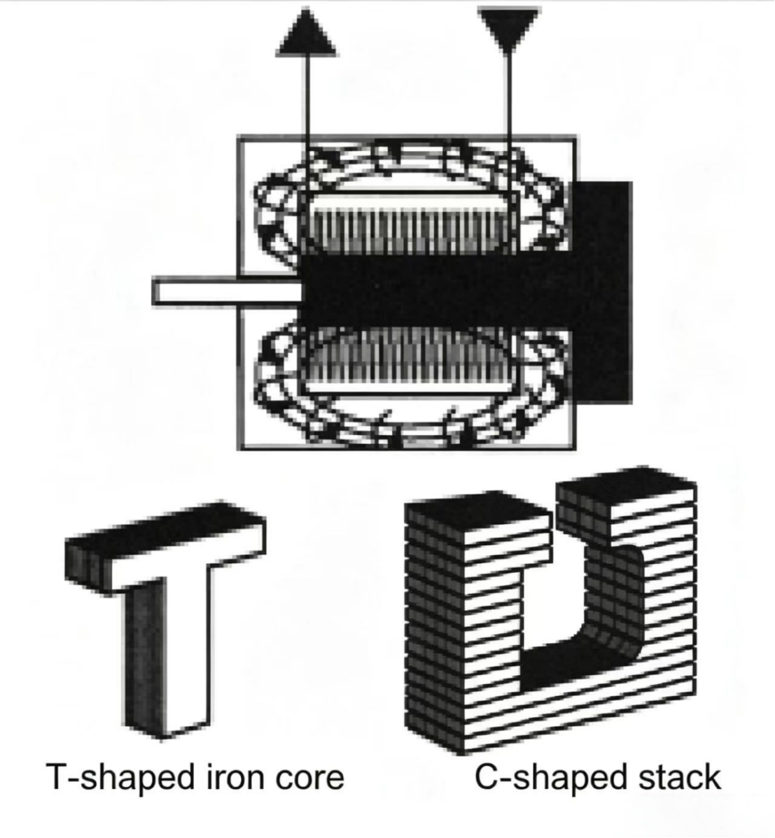
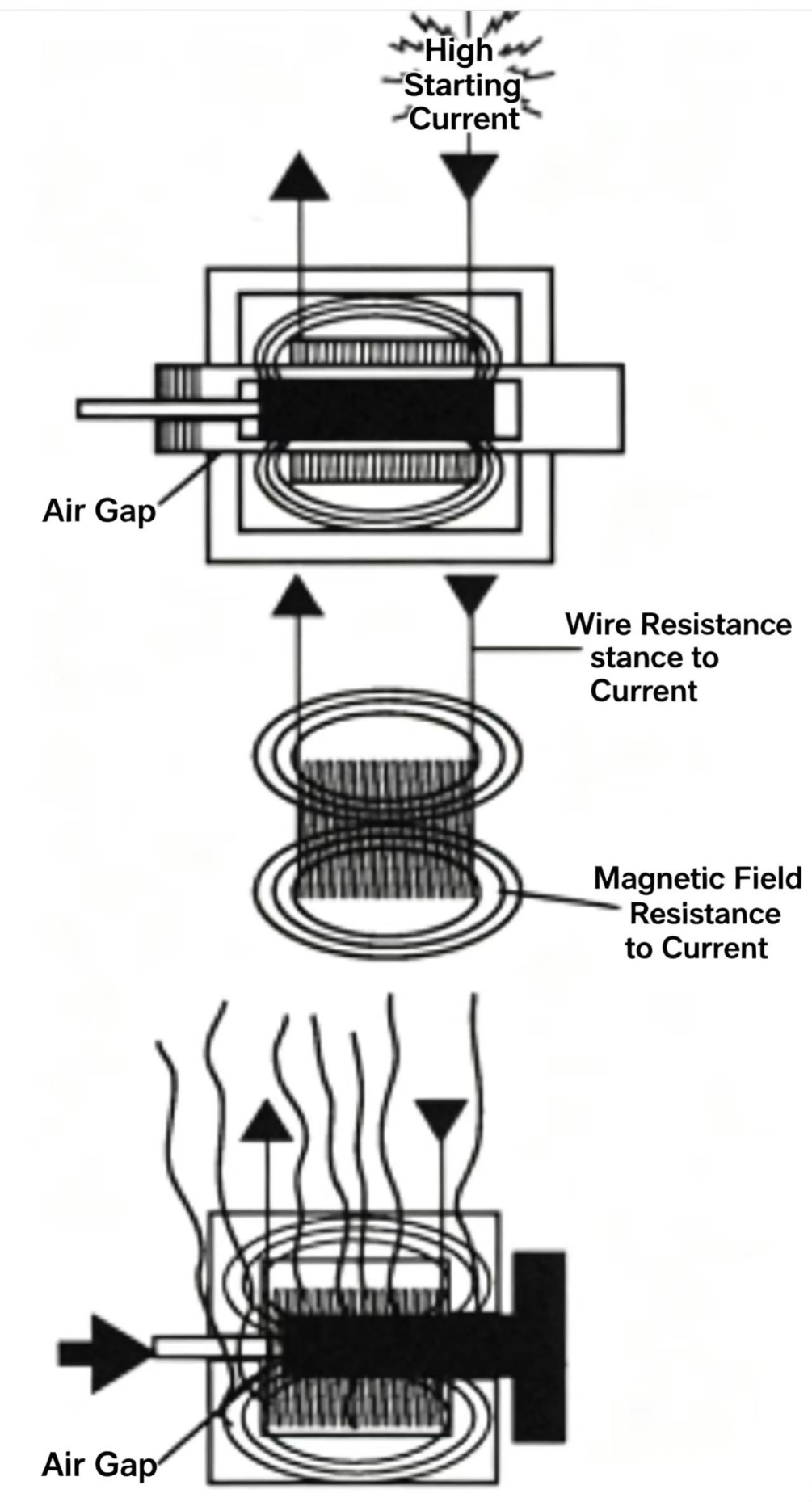
Figure 10-10 AC solenoid inrush vs holding current. When first energized, the large air gap allows high inrush current (several times holding). Once fully seated, impedance rises and current drops. A jammed spool (gap never closes) means sustained inrush current — guaranteed coil burnout.
A continuously-rated solenoid can remain energized for a long time without overheating. The solenoid's heat dissipation capability is sufficient to dissipate most of the heat generated by the smaller holding current through the coil. Most industrial hydraulic directional valves use continuously-rated solenoids.
Solenoid-controlled directional valves have some limitations. First, conventional solenoids cannot be used in wet or explosive environments. Second, when the directional valve service life must be especially long, electrically-controlled solenoids are usually also avoided. Perhaps the biggest drawback of solenoids is that the shifting force they can produce is limited. In fact, for larger directional valves, the shifting force required is quite large. For larger valves (1/4" or 3/8" / 6.35 mm or 9.5 mm), a solenoid directional valve is usually mounted on top, and during shifting, flow from the small valve is introduced to the corresponding side of the large valve spool. This type is called a solenoid-operated pilot directional valve.
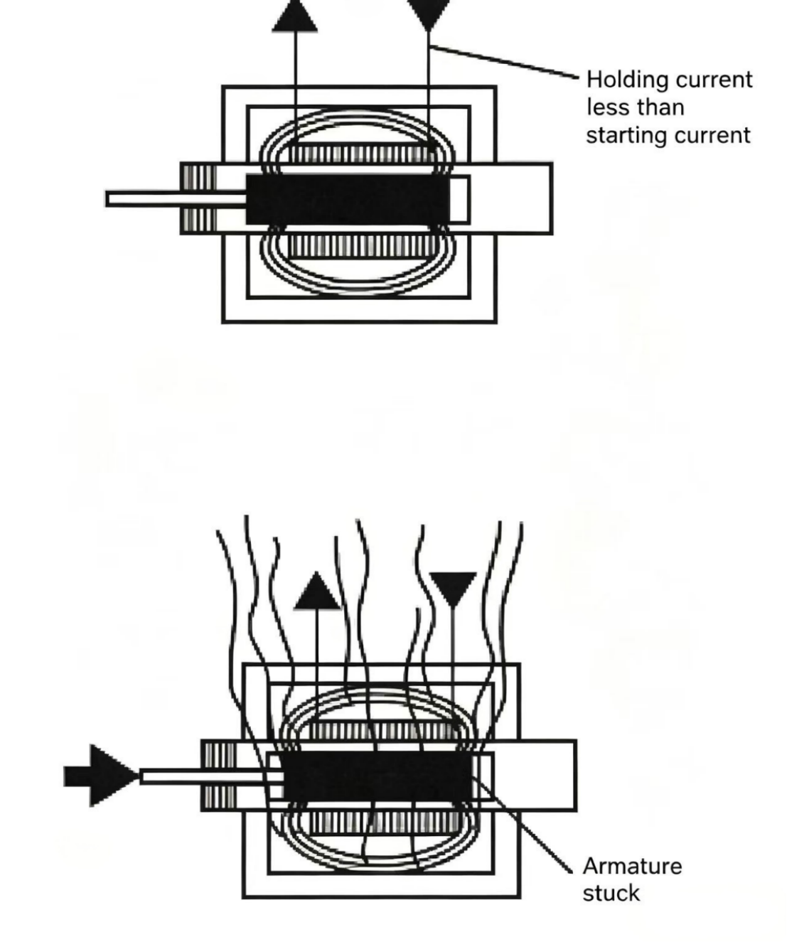
Heat is the main cause of direct-acting directional valve solenoid failure, usually caused by solenoid jamming, high ambient temperature, or low voltage (insufficient shifting force to fully seat the iron core or armature).
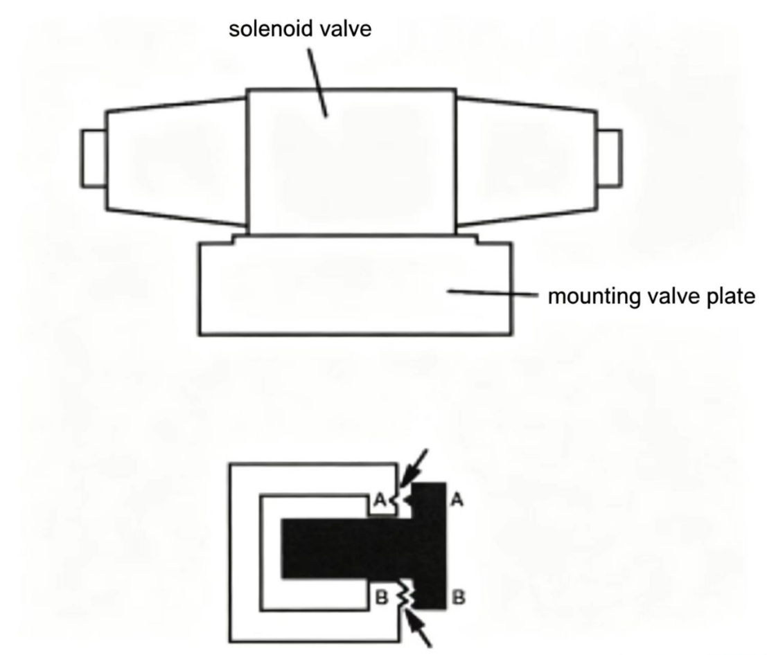
A jammed spool prevents the iron core or armature from fully seating, causing the solenoid coil to continuously draw very high inrush current. The solenoid cannot dissipate the enormous heat generated, eventually burning out the coil. Although excessive flow through the valve can jam the solenoid, mechanical interference with spool movement is the more common jamming cause. Contaminants (such as sludge, metal flakes, core sand, and PTFE tape) can jam the spool, or the spool can be jammed by burrs between the spool and valve body. Oil oxidation particles and oil varnish can build up on the spool, making the gap between spool and valve body disappear — cleaning with solvent can remove oil varnish. A warped mounting plate can also cause solenoid jamming — when mounting bolts are tightened, the valve body may bend slightly, limiting spool movement and burning out the coil. Mounting plate flatness requirements are typically within 0.0003–0.0005 in (0.00762–0.0127 mm).
For dry-type solenoids, as the solenoid iron core is pulled into the coil, wear occurs between the iron core and C-frame. When disassembling this type of solenoid, it is recommended to reinstall the iron core in its original position. Otherwise the worn portion cannot align properly, the iron core cannot fully seat, the solenoid makes a buzzing noise — indicating near failure.
Sometimes both solenoids in a dual-solenoid directional valve may be energized simultaneously — this means one iron core or armature fully seats while the other is jammed. The result is one solenoid coil burns out. Simultaneous energizing of both solenoids is usually caused by an electrical control device failure or wiring error.
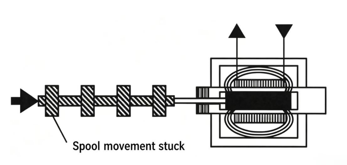
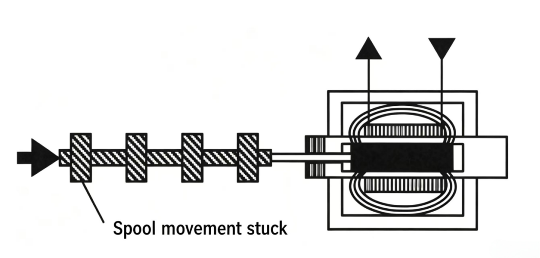
When current pulls the solenoid iron core or armature in, the heat generated must be dissipated from the coil. If surrounding air temperature is too high, heat dissipation is difficult and the coil may burn out. If ventilation is poor or equipment works near heat sources, this can occur.
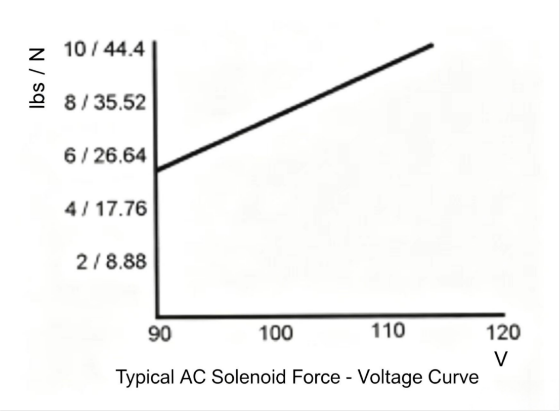
For a 110 V, 60 Hz solenoid, when line voltage drops to about 100 V, the electromagnetic force produced is insufficient to fully seat the iron core or armature within the design time period. Due to the extended inrush current time, the solenoid operates at higher temperature, eventually causing failure. Sometimes early signs of coil burnout are buzzing or vibrating noise. Low voltage problems often occur in many power-user plant environments. If low voltage is suspected, the power company can install a 24-hour recording meter to check actual conditions.
In previous examples, a two-position directional valve (with two end positions) has been discussed. In some applications a three-position directional valve is used. The third center position is a neutral or transition position. A three-position directional valve graphic symbol has three boxes — the center box represents the center position and the internal connections when the spool is at center.
The most common type of three-position directional valve is the spring-centered type. This valve has springs on both ends to hold the spool at the center position when neither solenoid is energized.
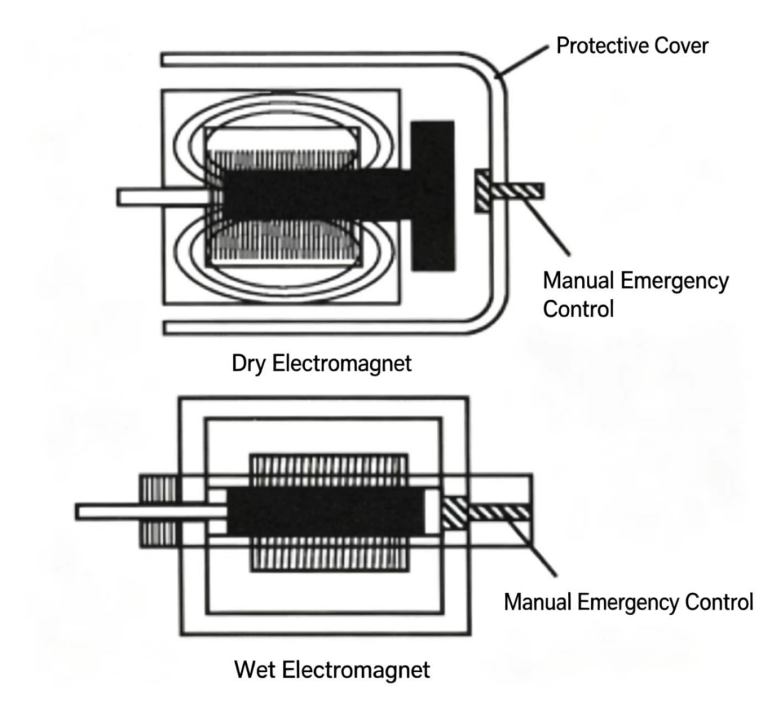
Figure 10-12 Three-position spring-centered directional valve. Springs hold the spool at center when both solenoids are de-energized. The center position determines what happens to the cylinder load when the machine is stopped.
Four common center position configurations exist. The choice of center condition determines circuit behavior when the directional valve is at center (neither solenoid energized):
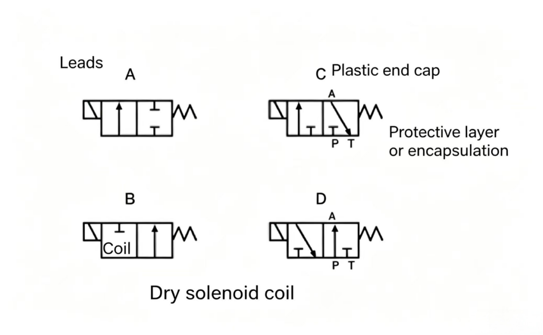
Figure 10-13 Four center position configurations. Choice depends on circuit requirements: whether the cylinder should hold position, float freely, or whether the pump should unload when the valve is centered.
Standard directional valves switch between discrete positions (open/closed). Proportional directional valves allow the spool to be positioned anywhere between fully open and fully closed, with a smooth relationship between the electrical input signal and the spool position and flow. This allows continuously variable control of both direction and flow rate with one valve.
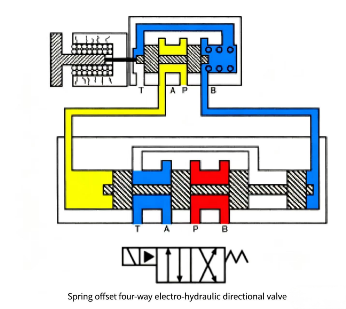
For large-flow applications where solenoid force is insufficient to directly shift the main spool, a pilot-operated design is used. A small solenoid-operated pilot valve directs pilot pressure to shift the larger main spool. This two-stage design allows small solenoids to control very large flow rates — the pilot valve does the switching, and the pilot pressure does the work of moving the main spool.
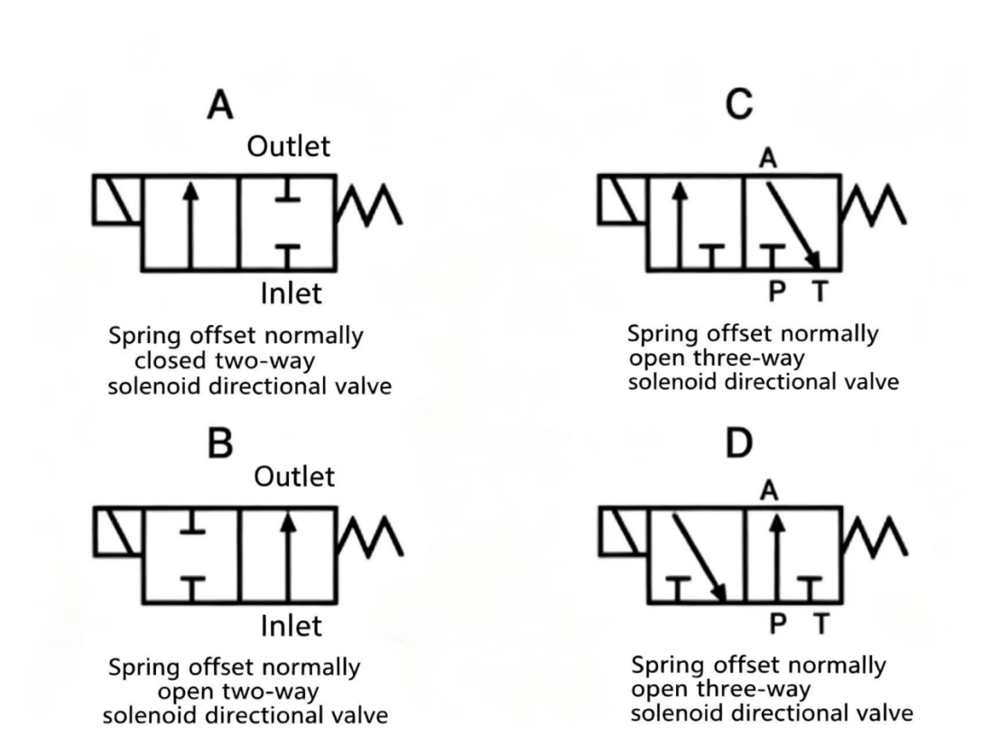
Figure 10-14 Pilot-operated directional valve. The small solenoid-operated pilot valve (top) routes pilot pressure to shift the large main spool (bottom). This design allows small solenoids to control high-flow main valves.
In the control device, reversing signal and input signal enter at the same time. The "error" signal produced between the two drives the control device to proportionally energize one solenoid "A" or "B." As the solenoid is energized, it converts the signal to a force. The proportional solenoid centered in the valve body, along with the bias spring of the pilot valve, converts that control pressure to a pilot spool position. The position sensor LVDT directly connects to the main valve spool, its function being to provide automatic feedback to the pilot spool.
The pressure-differential directional valve is a three-stage type — with the pilot valve as the first stage, the main valve as the second stage. The pilot valve is more complex, consisting of a torque motor, springs, jet pipes, and an adjustable spool with pilot end caps and an LVDT. The second stage (main valve) is similar to the other pilot-operated directional valves.
The pilot valve consists of a torque motor, jet pipe, spool with left and right springs, and similar components. The jet pipe directs control pressure to either end of the spool. The pilot valve is similar in type to the spring-centered directional valve.
The second stage (main valve) is similar to other proportional directional valve types and will not be repeated here.
Electrical control signal current flows through the torque motor windings between the two solenoids. The comparison and difference of the electrical signals determines the torque motor magnetic field direction. Depending on which solenoid has the stronger signal, the jet pipe is directed to pressurize one end of the pilot spool. At the same time, the output of the control device increases the flow to one side of the directional valve spool up to the proportional value, gradually increasing the flow to that side until the proportional value is reached.
Valve Type |
Passages |
Typical Use |
4-way directional valve |
P, T, A, B (4 passages) |
Reverse double-acting cylinder or motor |
3-way directional valve |
P, T, A (3 passages) |
Control single-acting spring-return cylinder |
2-way directional valve |
2 passages only |
On/off switching, safety interlock |
3-position spring-centered |
P, T, A, B + center |
Hold, float, or unload pump at center position |
Pilot-operated |
Main + pilot valve stages |
Large flow rates where solenoid force is insufficient |
Proportional directional |
Variable spool position |
Continuously variable direction and flow rate |
KEY CONCEPTS — AC SOLENOID FAILURE PREVENTION
Failure Cause |
Mechanism |
Prevention |
Jammed spool |
Sustained inrush current → coil burnout |
Keep oil clean; check mounting flatness; avoid PTFE tape on threads |
High ambient temperature |
Heat cannot dissipate from coil |
Improve ventilation; keep equipment away from heat sources |
Low voltage |
Inrush current sustained (core never seats) |
Check voltage under load; use voltage regulator |
Both solenoids energized |
One core seated, one jammed → burnout |
Check electrical control logic and wiring |

Welcome to HOVOO, a Chinese seal factory. Production of PU, Rubber and PTFE seals. The seals include O-ring, piston seal, rod seal, Gray ring and gas seal.


 EN
EN
 AR
AR CS
CS DA
DA NL
NL FI
FI FR
FR DE
DE EL
EL IT
IT JA
JA KO
KO NO
NO PL
PL PT
PT RO
RO RU
RU ES
ES SV
SV TL
TL IW
IW ID
ID LV
LV SR
SR SK
SK VI
VI HU
HU MT
MT TH
TH TR
TR FA
FA MS
MS GA
GA CY
CY IS
IS KA
KA UR
UR LA
LA TA
TA MY
MY
