33-99No. Mufu E Rd. Gulou District, Nanjing, China [email protected] | [email protected]
33-99No. Mufu E Rd. Gulou District, Nanjing, China [email protected] | [email protected]

In a pressure control valve, pressure adjustment is typically done by adjusting the pre-load force of the bias spring using an adjusting screw. Pressure changes as the screw is turned.
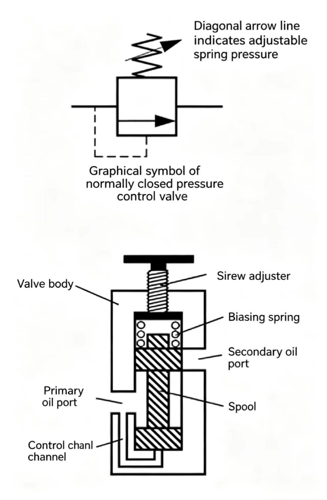
Figure 11-1 Normally closed pressure control valve. The adjusting screw sets the spring pre-load, which determines at what pressure the spool lifts and the valve opens.
In hydraulic systems, normally closed pressure control valves have several uses. Beyond being used as system relief valves, they can also control the sequence of actions — controlling one action to occur before another. They can also be used to balance external mechanical forces.
A normally closed pressure control valve that controls one action to occur before another is called a sequence valve.
In a hydraulic circuit that performs both clamping and drilling, the clamp cylinder must extend before the drill cylinder. To achieve this, the sequence valve is placed in the circuit just before the drill cylinder. The spring in the sequence valve does not allow the spool to connect the primary and secondary passages until the pressure rises high enough to overcome the spring force — until then, flow to the drill cylinder is blocked. So the clamp cylinder extends first. When the clamp contacts the workpiece, the pump must supply higher pressure to overcome the resistance. This raises the pressure above the pilot pressure acting on the sequence valve spool, connecting the primary and secondary passages, and flow goes to the drill cylinder — the drill cylinder then starts to move.
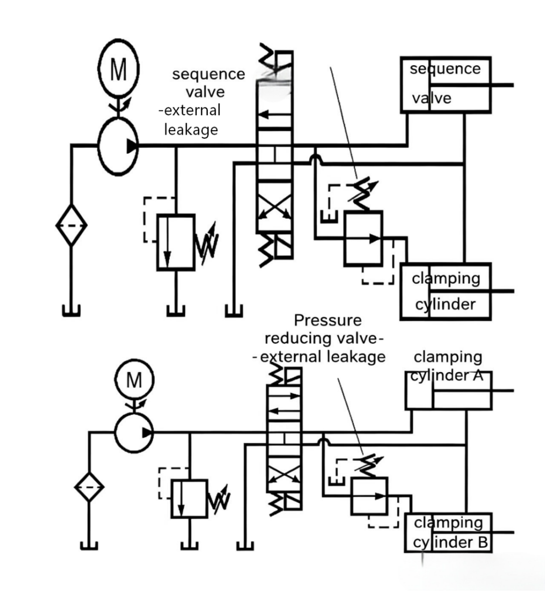
Figure 11-2 Sequence valve circuit. With the sequence valve blocking flow to the drill cylinder until system pressure builds up, the clamp always closes first before drilling begins.
A normally closed pressure control valve used to balance or support a weight (such as a press platen) is called a counterbalance valve.
In a press circuit, when the directional valve sends flow into the blind end of the cylinder, the press platen connected to the piston rod will fall uncontrolled under gravity, and the pump flow will be sucked dry. To prevent this, a normally closed pressure valve is installed downstream of the press cylinder. The valve's spool does not open the primary-to-secondary passage until the bottom pressure rises above the platen weight-generated pressure. In other words, while supplying oil to the blind end of the cylinder, this approach balances the platen weight throughout the full downward stroke.
The counterbalance valve can also be used to brake the rotational motion of a heavy-load hydraulic motor. For a hydraulic motor driving heavy wheels, once the wheels build momentum, the motor may overspeed (runaway). If a counterbalance valve is installed at the motor outlet, the valve only opens when the outlet pressure reaches the set value. This back-pressure counteracts the force generated by converting the heavy wheel's rotational momentum.
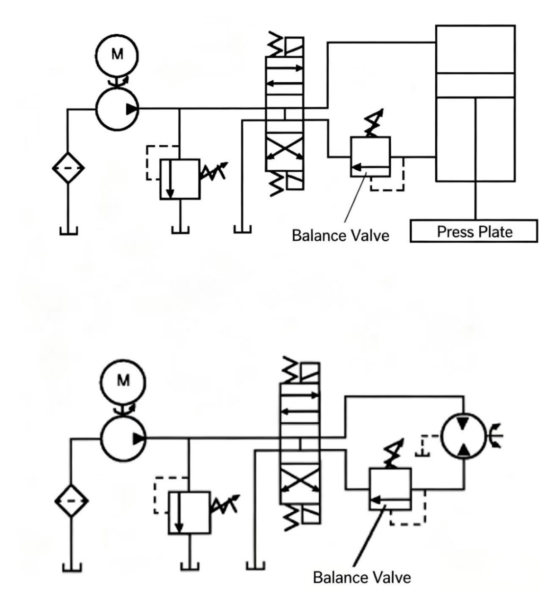
Figure 11-3 Counterbalance valve. (Top) Prevents press platen from falling uncontrolled. (Bottom) Prevents heavy-load motor from overspeeding when the load drives the motor.
A simple relief valve consists essentially of a valve body with a spool biased by a hard spring. When the pressure on the side of the spool opposite the spring rises high enough, the spool moves and opens a passage to divert pump flow to tank.
In the example circuit, the simple relief valve is set so that when pump outlet pressure reaches 1,000 psi (68.97 bar), 10 gpm (37.9 lpm) relief flow occurs. This does not mean the valve suddenly opens at 1,000 psi — rather, at pressures below 1,000 psi (68.97 bar), the valve starts to open at a low pressure point, diverting some flow to tank. As pressure approaches 1,000 psi (68.97 bar), the opening gradually increases to pass more flow to tank. At the 1,000 psi (68.97 bar) set point, the orifice opening is large enough to pass the full 10 gpm (37.9 lpm). When system pressure drops below the relief valve opening pressure, the passage to tank formed by the valve opening disappears from the circuit.
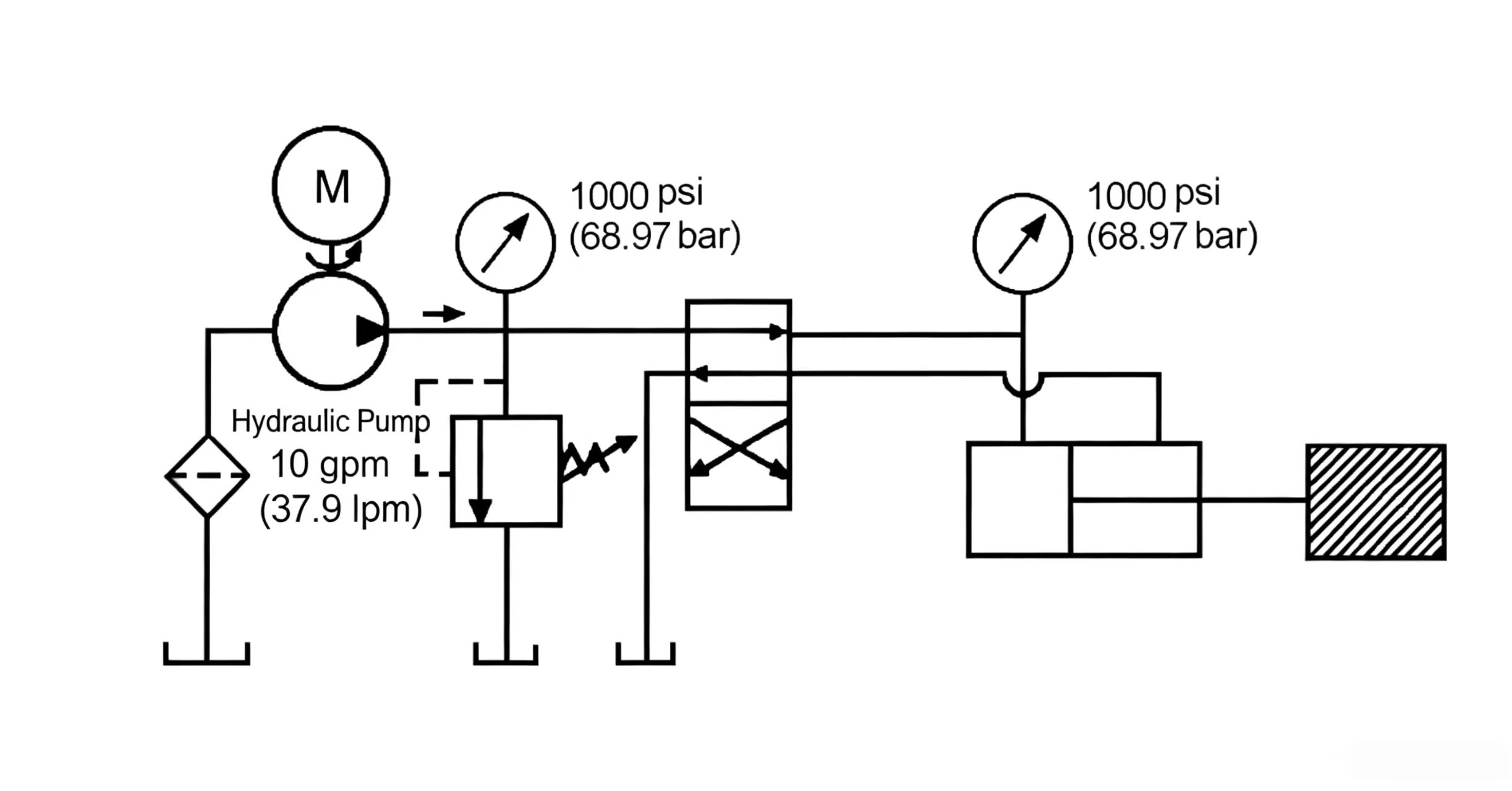
The opening of a relief valve is essentially an orifice function. Like any orifice device, the flow through it is affected by fluid temperature, and therefore by viscosity.
For a relief valve set at 1,000 psi (68.97 bar) to bypass 10 gpm (37.9 lpm), the assumption is that oil viscosity remains constant. At room temperature, equipment reservoir oil viscosity is 400–500 SUS (86.3–107.9 cSt). Under this viscosity, setting system relief at 1,000 psi (68.97 bar) bypasses 10 gpm (37.9 lpm) through the orifice opening. Once the oil heats up, the pump pressure may be limited to 900 psi (62 bar) or lower. The reason is that as oil temperature rises, viscosity drops — to, say, 100 SUS (21.6 cSt). This means a lower pressure force can push 10 gpm (37.9 lpm) of flow through the relief valve's opening to tank.
The reverse happens when the relief valve is set at working viscosity — when the pump starts up, oil temperature is low, viscosity high, and pump pressure may reach 1,100 psi (75.9 bar). For systems with strict maximum pump pressure limits, the system should be warmed up before adjusting the relief valve.
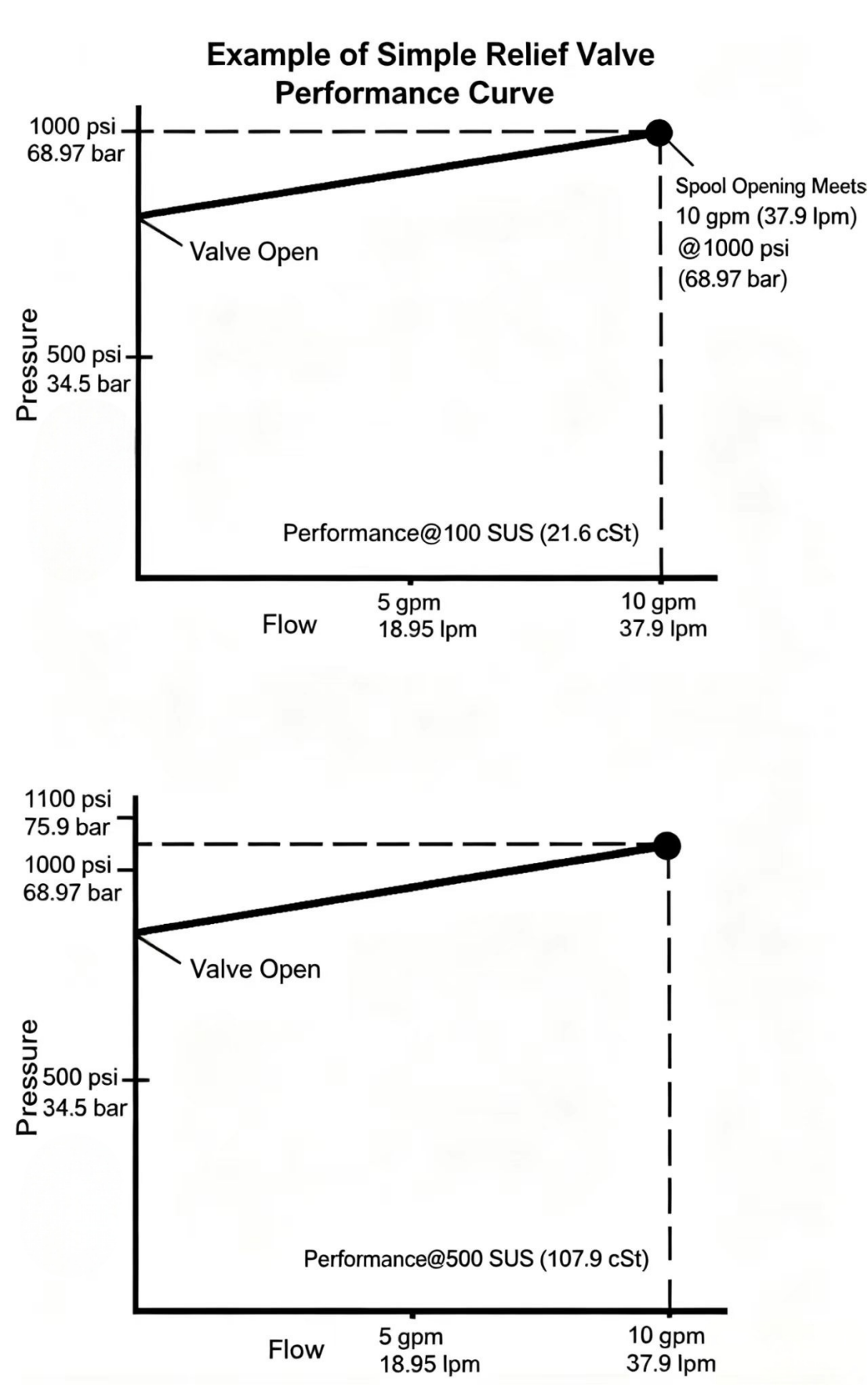
Figure 11-5 Temperature effect on relief valve setting. Cold (high viscosity) oil requires higher pressure to pass the same flow. Always warm the system before setting the relief valve.
Pump wear also affects the relief valve setting. For a relief valve set to bypass 10 gpm (37.9 lpm) at 1,000 psi (68.97 bar), as long as 1,000 psi (68.97 bar) pressure is provided at the valve's inlet port, 10 gpm (37.9 lpm) of pump flow can bypass through the valve's orifice to tank. As the hydraulic pump wears, its output flow decreases; the flow through the relief valve also decreases, so pressure also drops. For a valve set at 1,000 psi (68.97 bar) to bypass 10 gpm (37.9 lpm), when bypass flow decreases to 5 gpm (18.95 lpm) due to pump wear, system relief valve pressure may only be 900 psi (62 bar). When adjusting the relief valve setting, similar situations will occur.
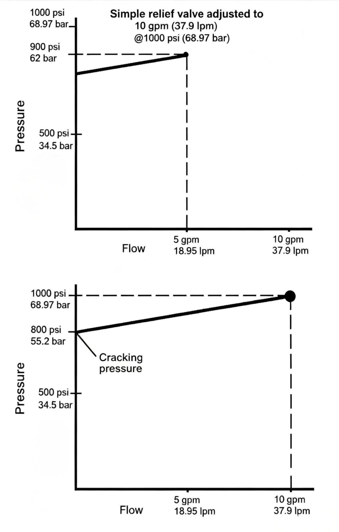
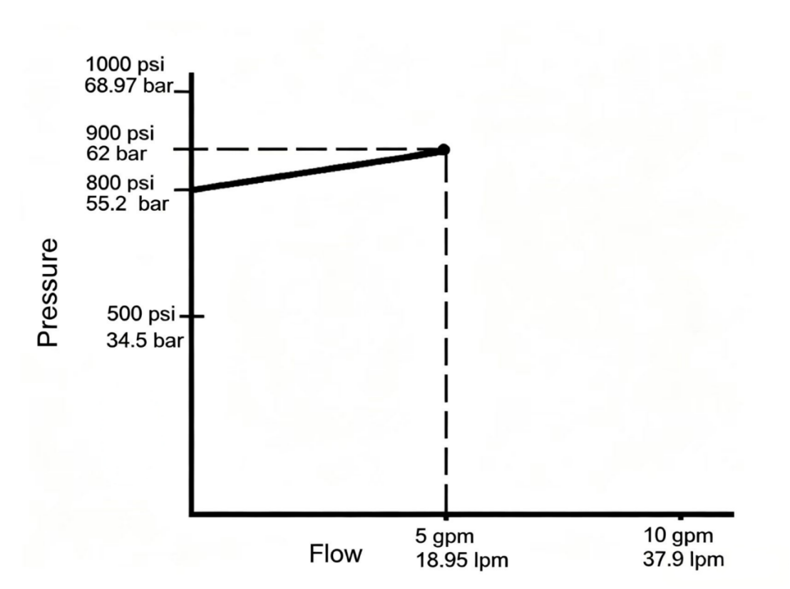
The cracking pressure is the pressure at which the relief valve begins to open its bypass passage. For a simple relief valve, this pressure is slightly lower than the relief valve set value. Simple relief valves have the characteristic of pre-cracking pressure.
In the simple relief valve performance curve diagram, the valve is set to bypass 10 gpm (37.9 lpm) at 1,000 psi (68.97 bar). The curve shows the valve opens at 800 psi (55.2 bar), and as pressure approaches 1,000 psi (68.97 bar), the bypass flow increases — finally at 1,000 psi (68.97 bar) the orifice opening is large enough to pass 10 gpm (37.9 lpm).
The pre-cracking pressure of the relief valve is a disadvantage to the system. Suppose the pump/motor produces 750 psi (51.7 bar) and delivers 10 gpm (37.9 lpm) to the actuator, where 550 psi (37.9 bar) is needed for the load and the remaining 200 psi (13.8 bar) overcomes fluid resistance. Using a simple relief valve set at 1,000 psi (68.97 bar), at this point the valve stays closed and all pressure oil goes directly to the working load.
If the load pressure rises to 700 psi (48.28 bar), the pump/motor must raise its output to 900 psi (62.1 bar) (assuming constant output flow). Since the cracking pressure of the relief valve is 800 psi (55.2 bar), at the current pump pressure 5 gpm (18.95 lpm) is bypassed, meaning the actuator gets less than the full pump flow, completing the action at a reduced speed. At the same time, oil flows through the relief valve orifice and generates unnecessary heat.
If the load pressure is 750 psi (51.7 bar), the pump/motor needs to produce 950 psi (65.5 bar) — even higher pressure with more flow bypassing through the relief valve orifice, actuator speed drops further, and even more unnecessary heat is generated.
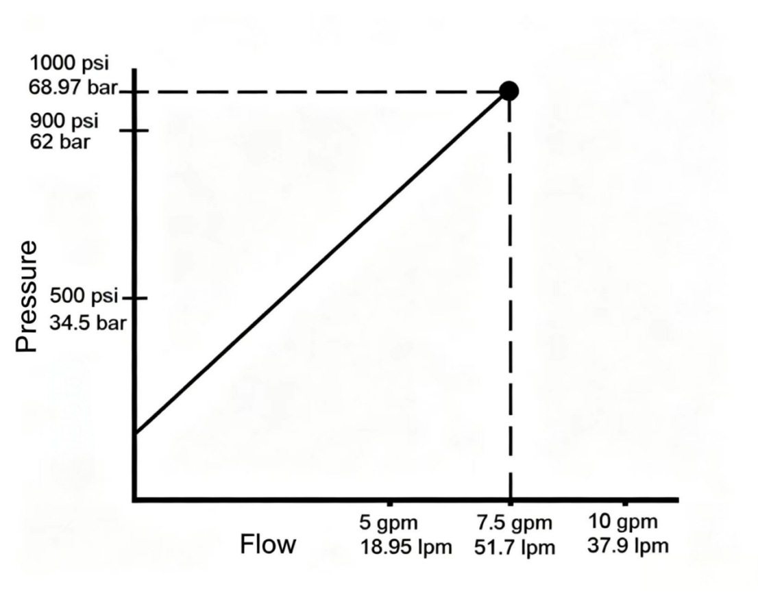
Figure 11-7 Pre-cracking pressure effect. The simple relief valve begins bypassing flow before the set pressure is reached, reducing actuator speed and wasting energy as heat at intermediate load pressures.
The normally closed pressure control valve has its primary and secondary ports disconnected at normal position, sensing primary port pressure. The normally open pressure valve has its primary and secondary ports connected at normal position, sensing secondary port pressure.
The reducing valve is typically a normally open pressure control valve.
A reducing valve operates by sensing the pressure downstream of the valve. When downstream pressure equals the valve setting, the spool partially closes, forming an orifice that converts the excess upstream pressure energy to heat. If downstream pressure drops, the spool opens wider, allowing pressure to rise again.
The example clamping circuit requires clamp cylinder B to apply less force than clamp cylinder A. To achieve this, a reducing valve is installed just before clamp cylinder B to reduce the pressure going to cylinder B to the reducing valve setting. At this set pressure point, the reducing valve spool action creates an orifice function, converting excess upstream pressure energy to heat. Cylinder B clamps at the reduced pressure.
The reducing valve secondary port pressure at rated flow conditions is lower than at zero-flow conditions. The difference between the two reduced pressures is the static pressure drop offset of the reducing valve. Static drop is an inherent characteristic of the reducing valve that further explains why pressure increases with flow. A 15 gpm (56.85 lpm) rated reducing valve at rated flow and rated working pressure has a static drop offset of about 50 psi (3.45 bar), while a 100 gpm (379 lpm) reducing valve may have a static drop offset as high as 150 psi (10.3 bar).
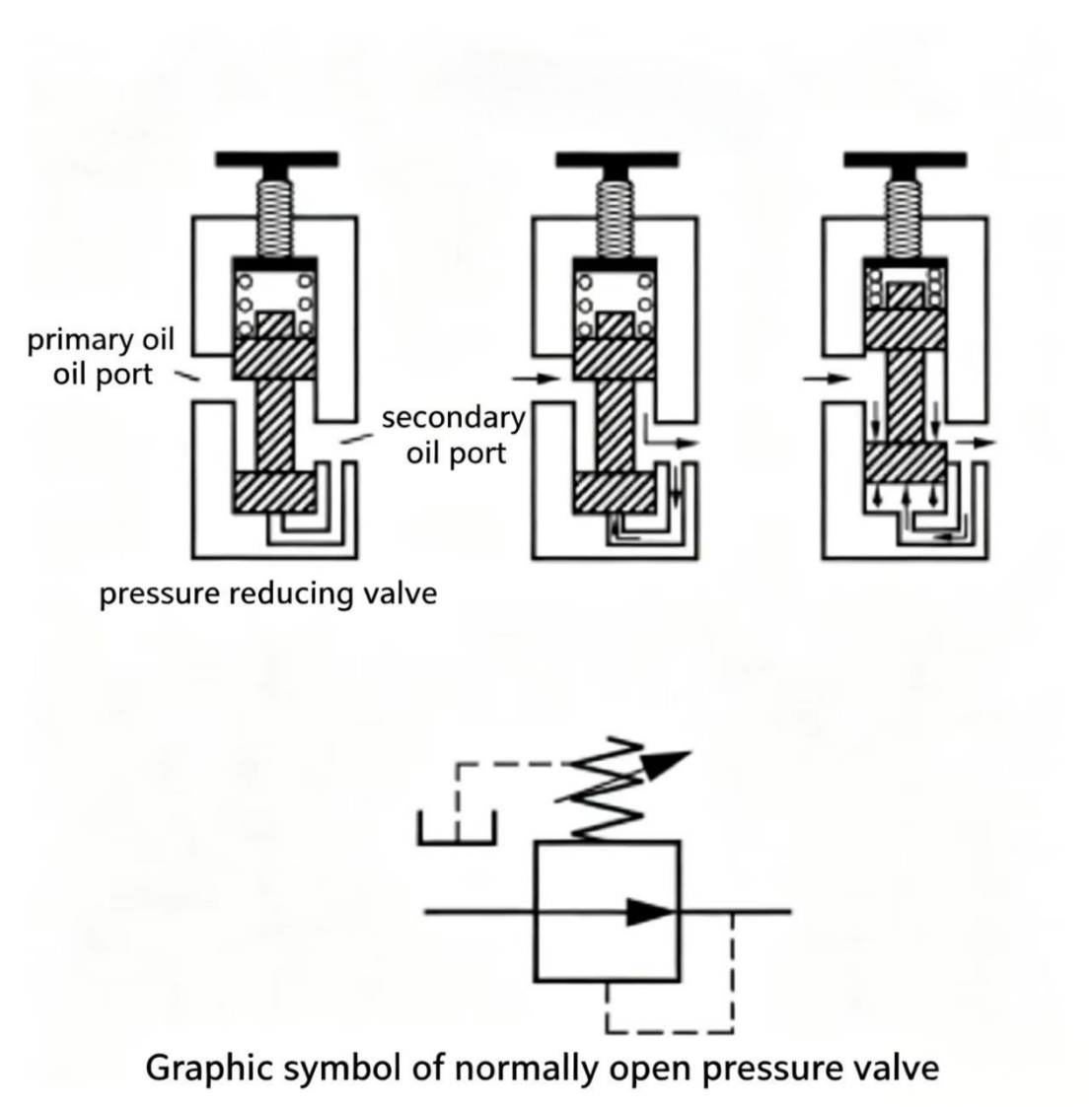
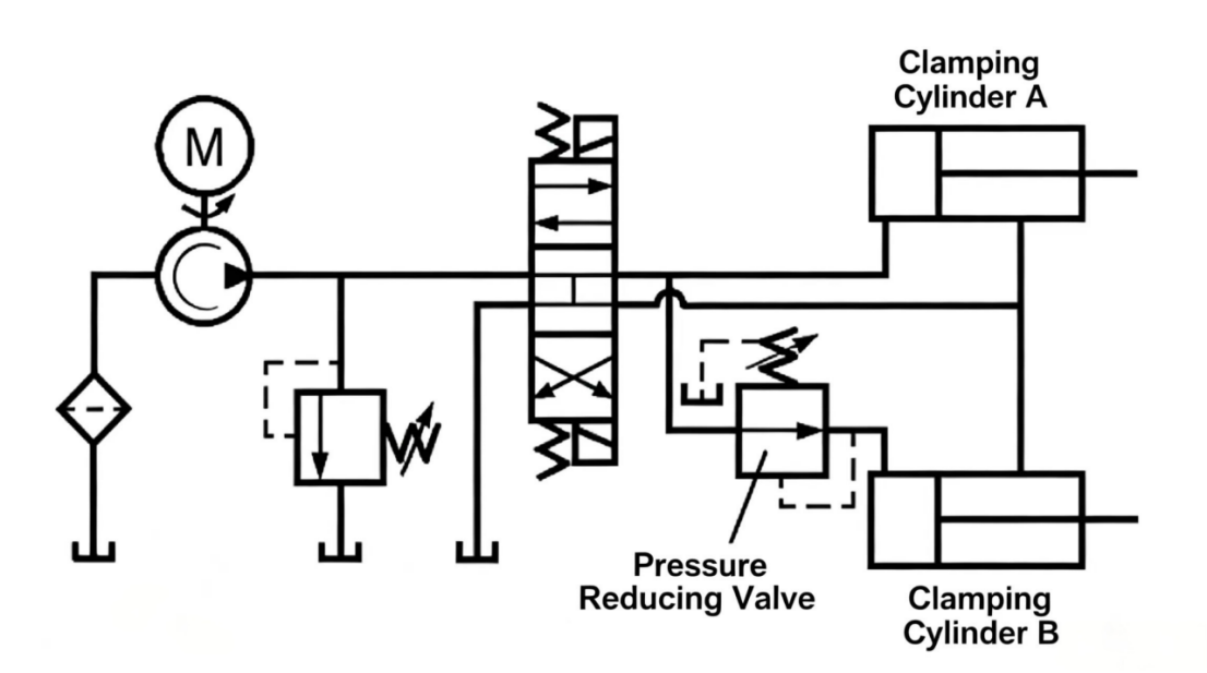
Figure 11-9 Reducing valve static pressure drop. The outlet pressure is slightly lower during flow than when flow stops. The larger the valve rated flow, the larger this offset.
As the pressure control valve spool moves inside the valve body, some pressurized oil leaks into the cavity above the spool. For the valve to function properly, the cavity above the spool must continuously drain oil to prevent blocking spool movement. Drain is achieved by building a drain passage inside the valve body and connecting it to the reservoir.
If the secondary port of the pressure valve connects to the reservoir — as with relief valves and counterbalance valves — the drain passage connects internally to the secondary port (return port). This is called internal drain.
If the secondary port of the pressure valve is a pressure port (the working port), as with sequence valves and reducing valves, the drain passage is a separate line to the reservoir. This is called external drain. Sequence valves and reducing valves are typically external-drain pressure control valves.
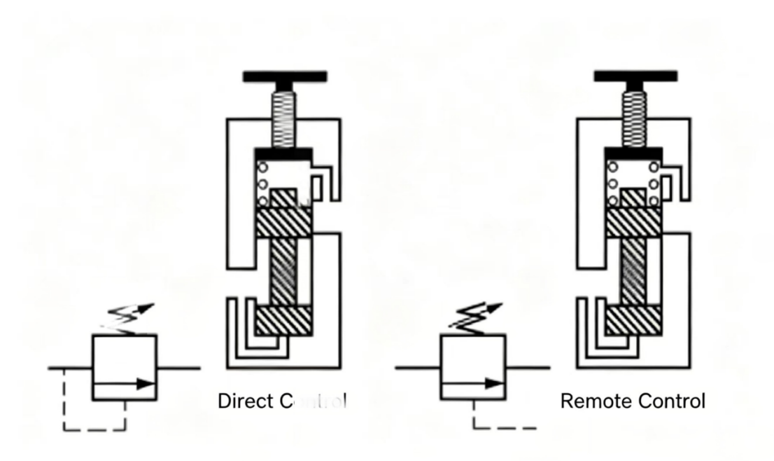
So far, pressure sensing has been through passages inside the valve body. Normally, for normally closed valves, sensing is at the primary port; for normally open valves, at the secondary port. This form of pressure sensing is called direct control or local control. A pressure control valve can also sense pressure from another part of the system through an external pipe — this is called remote control or pilot control.
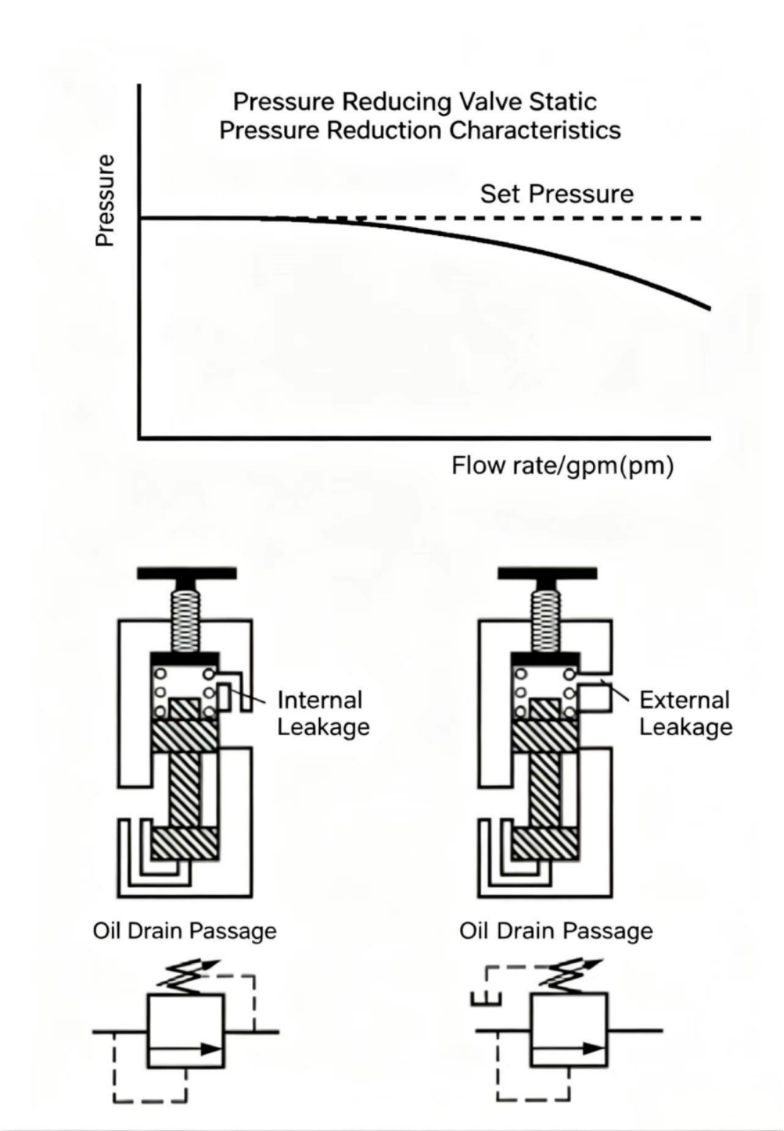
Figure 11-10 Direct control (left) senses pressure at the valve's own port. Remote control (right) allows a distant pressure signal to open or adjust the valve — useful for accumulator unloading and multi-actuator sequencing.
An unloading valve is a remotely controlled normally closed pressure control valve. When the system pressure at the sensing point reaches a pre-set value, the valve diverts flow to tank.
In the accumulator circuit with a direct control pressure valve, once the accumulator charges to the valve set pressure, pump output flow returns to tank at the relief valve setting. This wastes significant power and generates large amounts of unnecessary heat. Connecting the control line to the check valve downstream unloading valve — so when the accumulator charges to the valve set pressure, the control pressure opens the valve, routing pump flow to tank at the lowest pressure. At this time, the pump does not need to supply high pressure to keep the unloading valve open, because the control pressure comes from the accumulator isolated by the check valve. Since the pump pressure at this point is negligible, the power loss is also negligible.
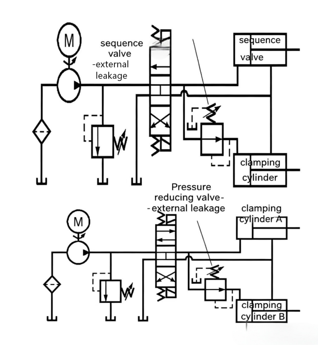
Figure 11-11 Unloading valve circuit. When the accumulator is charged, the check valve isolates it from the pump, and the unloading valve routes pump flow to tank at minimal pressure — saving nearly all the pump power during standby.
A direct-acting counterbalance valve installed downstream of the cylinder supporting the press platen can effectively balance or cancel the platen weight. But during the pressing process, when the platen passes through material, the platen weight should not add to the total pressing force. If this is not desired, the counterbalance valve should use remote control, with its control line connected to the other cylinder working line. Using a remote-controlled counterbalance valve, the platen is still balanced during downward travel, but during the pressing process the platen weight can be used for pressing force. During the entire downward stroke, when in idle stroke, the platen's self-weight tries to pull the cylinder rod down, upstream pressure and control line pressure drop, the counterbalance valve tends to close, increasing resistance, preventing flow from keeping up with the downward speed; in the pressing process, the counterbalance valve is opened wide by high upstream control pressure, with no back-pressure on the rod side, so the platen weight can add to the pressing force.
Note: The circuit shown is a simplified diagram. The actual circuit requires improvement to achieve stable operation.
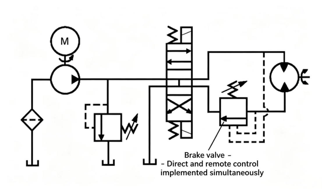
In the hydraulic motor circuit shown, a direct-acting counterbalance valve is used to brake the rotational inertia of the heavy-load. The counterbalance valve is set at 800 psi (55.2 bar), always providing back-pressure to the rotating load, so the load speed cannot exceed the pump flow and cause overspeed. However, this also means that the motor inlet pressure must exceed the load working pressure plus 800 psi (55.2 bar) — this is a disadvantage. To overcome this, a brake valve can be used instead.
A brake valve is a normally closed pressure control valve with both direct and remote control ports. Both control methods are connected simultaneously. Brake valves are commonly used with hydraulic motors and replace direct-acting counterbalance valves in hydraulic motor circuits.
The brake valve consists of a valve body, spool, control piston, bias spring, and spring adjusting device. The valve body has primary, secondary, internal control, and external control passages.
The brake valve is a normally closed valve. Assume the bias spring is set for 800 psi (55.2 bar) direct control opening. When the internal control passage pressure reaches 800 psi (55.2 bar), the control piston moves up and pushes the spool, opening the brake valve. When pressure drops below 800 psi (55.2 bar), the valve closes. This action is identical to the direct-acting counterbalance valve. The internal control piston area is much smaller than the spool cross-section area — the area ratio is typically 8:1. The external control port is generally connected to the motor's other working line. External pressure acts on the opposite end of the spool spring cavity — only 100 psi (6.89 bar) is needed to open the valve, because it acts on the spool bottom end, which has 8 times the area of the control piston.
Assume the brake valve is set at 800 psi (55.2 bar) direct control. When the motor inlet line pressure reaches 100 psi (6.89 bar), the brake valve opens, and the motor inlet pressure will be fully used to turn the load (assuming 100 psi / 6.89 bar is higher). If the load overruns, the motor inlet pressure drops, the brake valve closes, and the back-pressure of 800 psi (55.2 bar) reopens, increasing resistance and slowing the load.
The brake valve is a normally closed pressure control valve. Its action is directly related to the needs of the motor load.
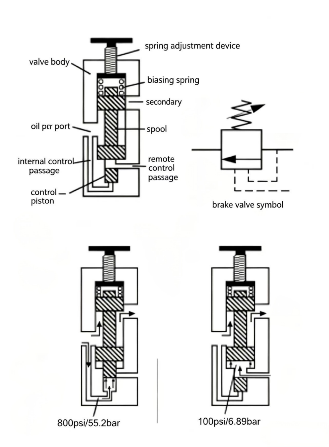
Figure 11-13 Brake valve. Unlike a simple counterbalance valve, the brake valve has both direct (internal) and remote (external) control. The 8:1 area ratio means only 100 psi external pilot pressure is needed to open it — so the motor can easily drive the load, while still providing 800 psi back-pressure braking when the load tries to overspeed.
Except for relief valves and unloading valves, all pressure valves typically require reverse flow to be able to pass freely. Normally closed pressure valves sense primary port pressure — if flow reverses, the primary port pressure drops, the spool closes, and the primary-secondary connection is cut off. Since reverse flow cannot pass through normally closed pressure valves, a check valve must be used to bypass this type of valve.
Normally open pressure valves sense secondary passage pressure — as long as flow reverses, the downstream pressure stays below the set value, the valve passage always stays open, so no reverse check valve is needed. However, in practice, once the secondary port pressure rises above the set value, the spool suddenly closes. As a precaution, check valves and reducing valves are commonly used together to ensure reverse flow.
From this chapter's study, we can summarize the key rules for pressure control valves:
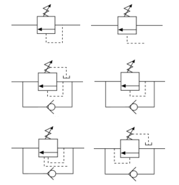
Figure 11-15 Graphic symbols for all pressure control valves. Note: sequence valves and reducing valves always have external drain lines (shown as dashed lines to tank). Relief, unloading, and counterbalance valves use internal drain.
Key terms used with pressure control valves:

Welcome to HOVOO, a Chinese seal factory. Production of PU, Rubber and PTFE seals. The seals include O-ring, piston seal, rod seal, Gray ring and gas seal.


 EN
EN
 AR
AR CS
CS DA
DA NL
NL FI
FI FR
FR DE
DE EL
EL IT
IT JA
JA KO
KO NO
NO PL
PL PT
PT RO
RO RU
RU ES
ES SV
SV TL
TL IW
IW ID
ID LV
LV SR
SR SK
SK VI
VI HU
HU MT
MT TH
TH TR
TR FA
FA MS
MS GA
GA CY
CY IS
IS KA
KA UR
UR LA
LA TA
TA MY
MY
