33-99No. Mufu E Rd. Gulou District, Nanjing, China [email protected] | [email protected]
33-99No. Mufu E Rd. Gulou District, Nanjing, China [email protected] | [email protected]

A check valve consists mainly of a valve body with inlet and outlet ports, and a spring-biased movable part. The movable part can be a disc, plate, or poppet — in hydraulic systems it is most often a ball or poppet seat.
Fluid can only flow through a check valve in one direction — the free-flow direction. When the system pressure at the inlet port rises high enough to overcome the spring force biasing the poppet, the poppet is pushed off its seat and fluid flows through. This is the free-flow direction. When fluid tries to flow back from the outlet port, the poppet is pushed onto its seat, sealing the passage and blocking reverse flow.
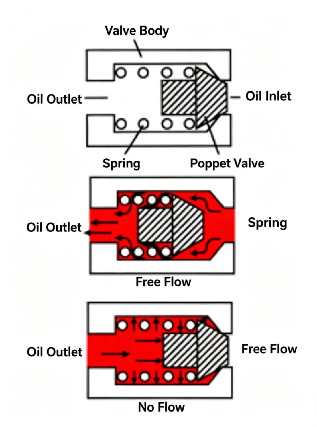
Figure 8-1 Check valve. The spring-loaded poppet seats when flow reverses, blocking reverse flow completely. The check valve is the hydraulic equivalent of a one-way street.
A check valve has both directional and pressure control functions — it allows flow in one direction only. In hydraulic systems, check valves are commonly used as bypass valves, allowing flow to bypass a component. For example, a check valve in parallel with a flow control valve allows reverse flow to bypass the flow control.
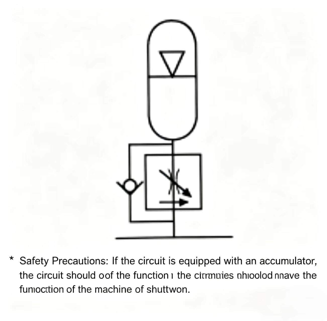
Check valves can also isolate a branch or component of a system. For example, with an accumulator: the check valve prevents the accumulator from discharging back through the relief valve or hydraulic pump.
SAFETY: When check valves are used in accumulator circuits, the circuit must have a mechanism to automatically unload the accumulator when the machine is shut off.
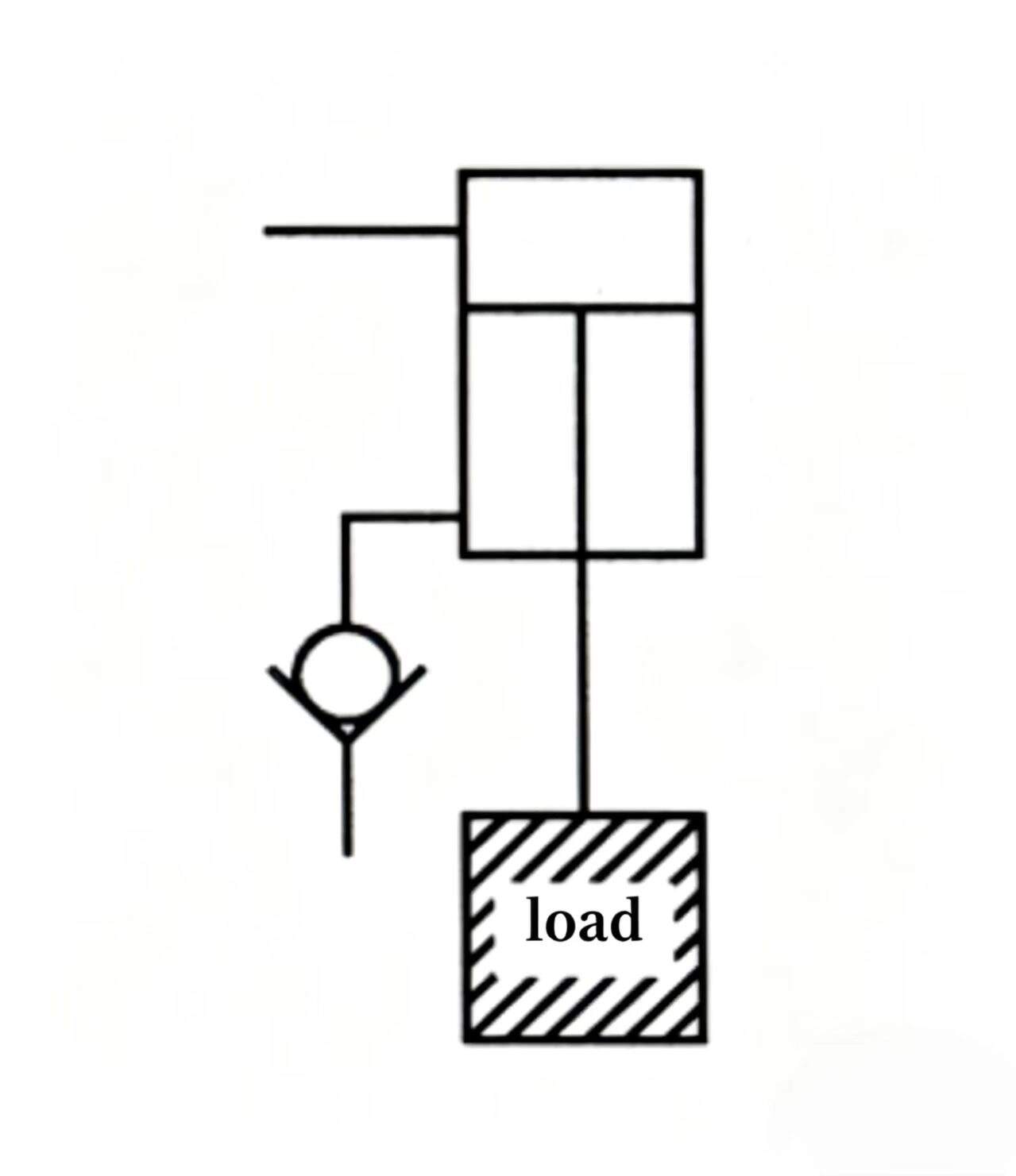
A check valve is generally a low-leakage device; in fact, it can be designed to be completely leak-free. A check valve can hold a load almost indefinitely. However, remember that a check valve is a one-way valve — to release the load, the movable part must be forced off its seat. This requires a special type of check valve called a pilot-operated check valve.
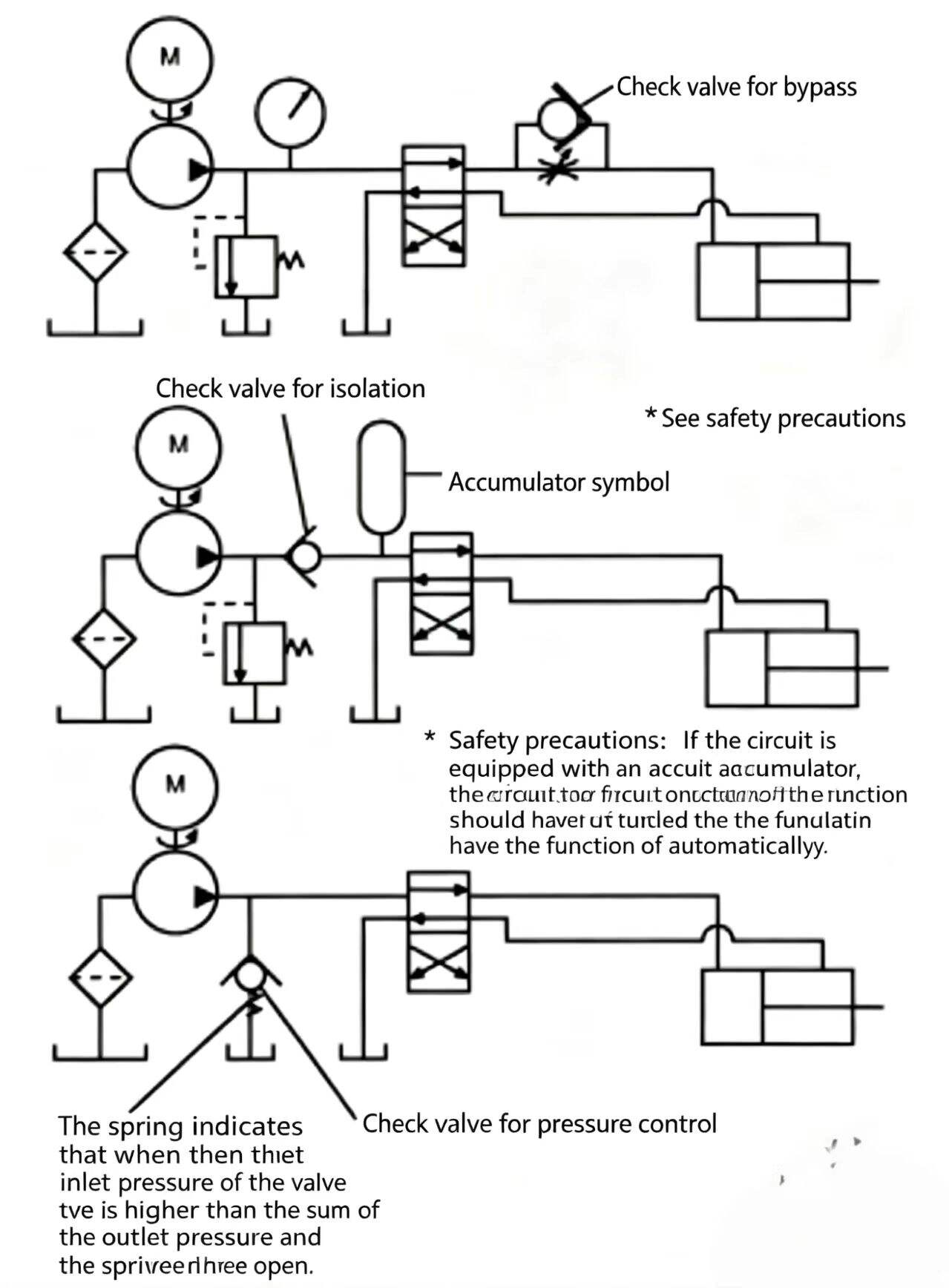
Figure 8-2 Three common uses for check valves in hydraulic circuits: bypass around a flow control, isolation of an accumulator, and spring-loaded pressure threshold.
Most spool-type hydraulic components have some internal bypass flow — this does not indicate poor quality, as most of this bypass flow is actually designed in to lubricate the component. However, if a system requires a cylinder to hold a load suspended without creeping, leakage becomes a problem. In this situation, a check valve with sealing capability must be used.
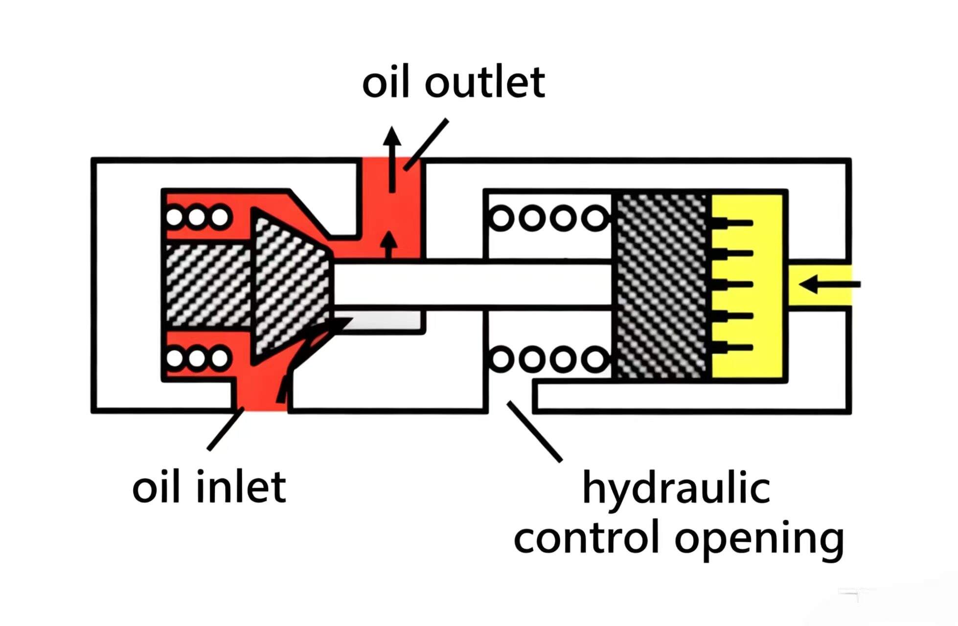
A pilot-operated check valve allows free flow in one direction; when a pilot pressure forces the movable part off its seat, reverse flow can also pass through.
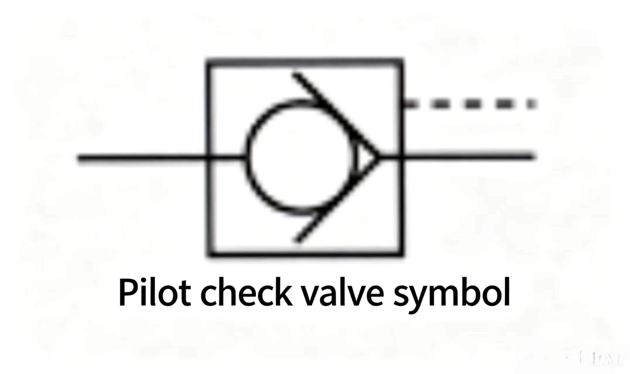
Like a regular check valve, a pilot-operated check valve has a valve body with inlet and outlet ports, a spring-biased poppet (movable part) against a seat. Additionally, directly opposite the seat, the poppet is fitted with a push rod and a soft-spring-biased pilot piston. Pilot pressure from the pilot port acts on the piston. The spring cavity at the piston has a drain port.
A pilot-operated check valve allows free flow from inlet to outlet in the same way as a regular check valve. Flow trying to enter from the outlet is forced to seat the poppet, closing the passage. When sufficient pilot pressure acts on the pilot piston, the piston moves and pushes on the check poppet, lifting it off its seat. As long as the force on the pilot piston is large enough, flow can pass from outlet to inlet.
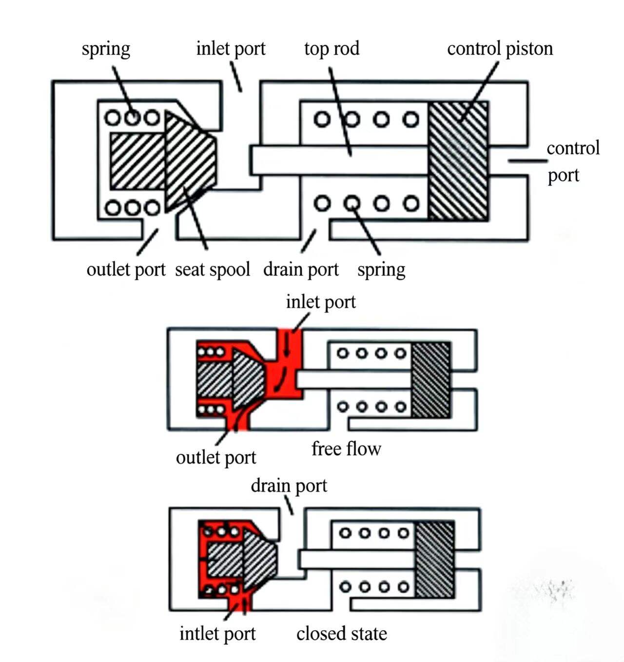
Figure 8-3 Pilot-operated check valve. Without pilot pressure it acts like a regular check valve (free flow one way only). With pilot pressure applied, reverse flow is also permitted — enabling load release.
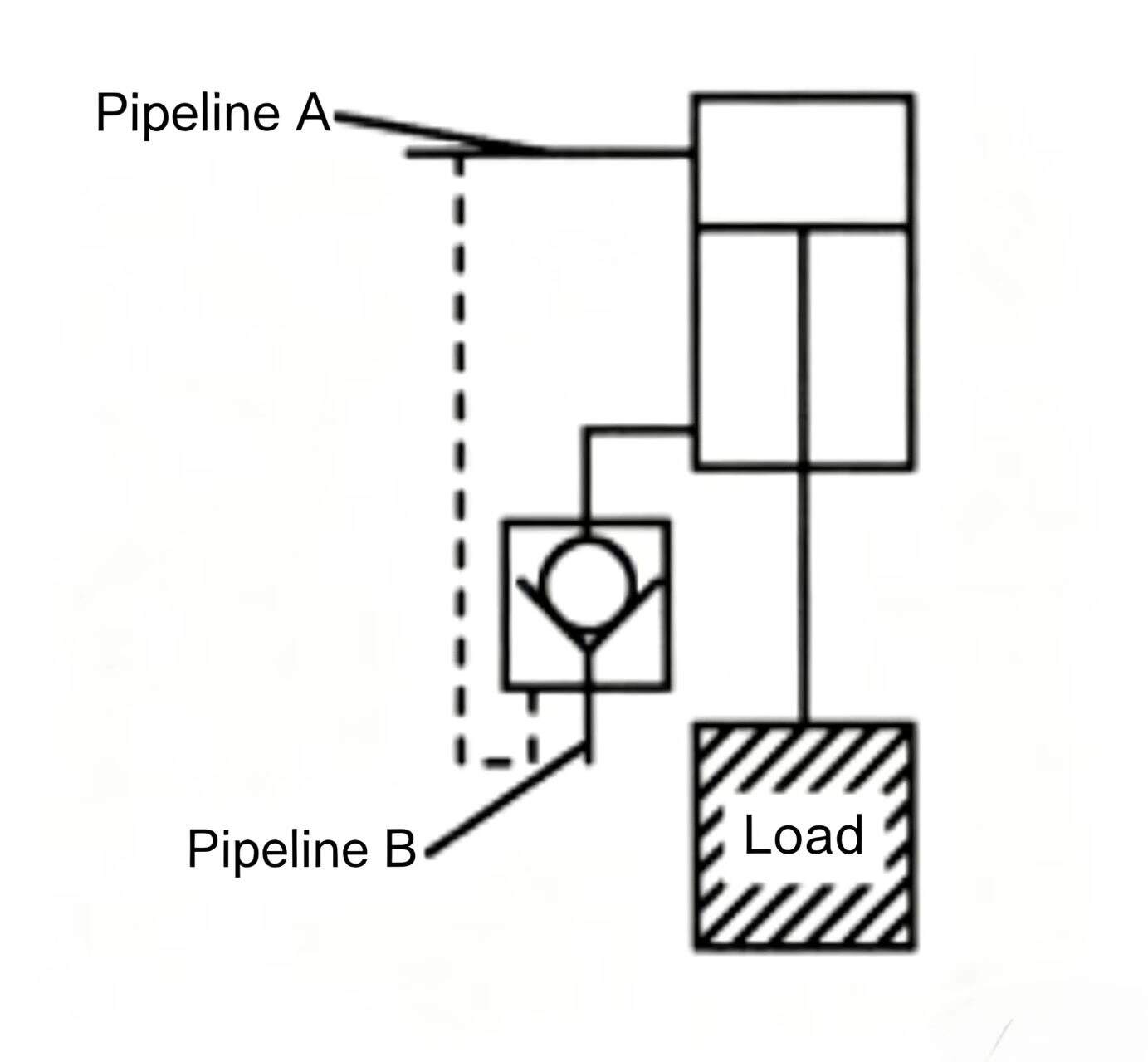
Using one pilot-operated check valve to seal off the flow from the cylinder's B-port keeps the load suspended as long as the cylinder seals are effective, with no leakage in the lines, cylinder, or check valve. To lower the load, just pilot pressure from line A into the control piston.
The pilot pressure for the pilot-operated check valve is taken from the working line of the hydraulic cylinder — as long as the pressure in line A is high enough, the check valve stays open. When the load is being raised, oil easily passes through the check valve because that is the free-flow direction.
In some situations, loads attached to the cylinder piston rod must be locked motionless. To achieve this, a pilot-operated check valve can be installed in each cylinder working line — the pilot-operated check valves seal off the flow leaving the cylinder. As long as the cylinder seals remain effective and there is no leakage anywhere, the load can be held in position.
For absolute load locking, a special locking cylinder with a mechanical lock device must be used. Mechanical locking is the safest load-holding method.
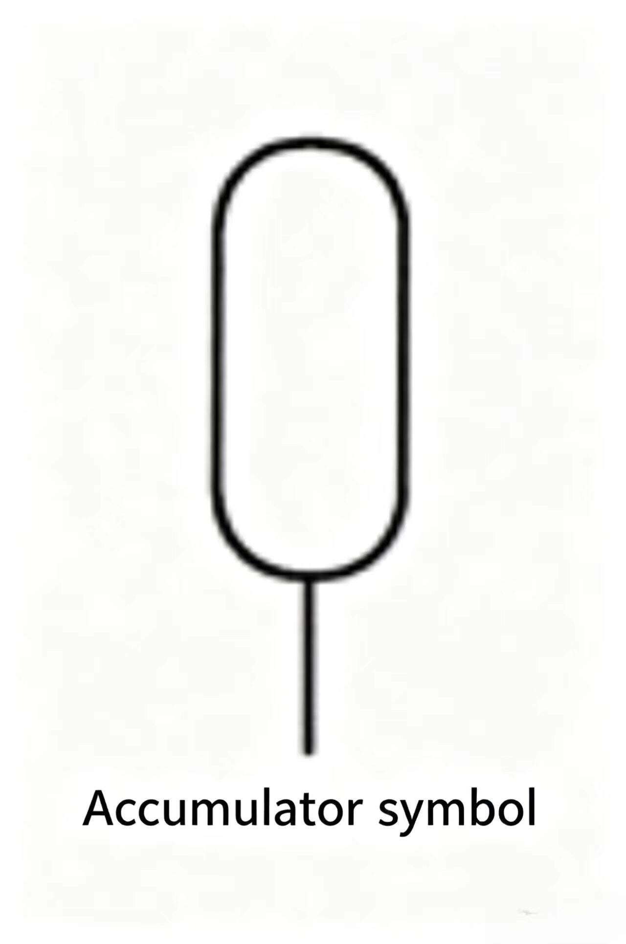
An accumulator stores hydraulic pressure. This hydraulic pressure is potential energy that can be converted to working energy (flow and pressure).
Accumulators can be divided into gravity-loaded, spring-loaded, and fluid/gas types. They differ in how the accumulator maintains the working force on the stored oil.
A gravity-loaded accumulator uses the weight of a heavy object acting on a piston or plunger to maintain working force on the stored oil. The weight can be made from any heavy material — iron, concrete, or even water. Gravity-loaded accumulators are generally very large, sometimes holding hundreds of gallons. They serve multiple hydraulic systems simultaneously and are used in rolling mills and central hydraulic systems.
The desirable characteristic of a gravity-loaded accumulator is that it stores oil at a relatively constant pressure — whether the container is full or nearly empty, the stored pressure is essentially unchanged. This is because the force acting on the oil is gravity (weight), which is constant — no matter how much oil is in the accumulator, the force applied is the same.
An undesirable characteristic of gravity-loaded accumulators is the production of shock. When a gravity-loaded accumulator is suddenly stopped during rapid flow output, the inertia of the heavy weight creates significant pressure spikes in the system. This can cause pipe and fitting leaks and can cause metal fatigue leading to premature component failure.
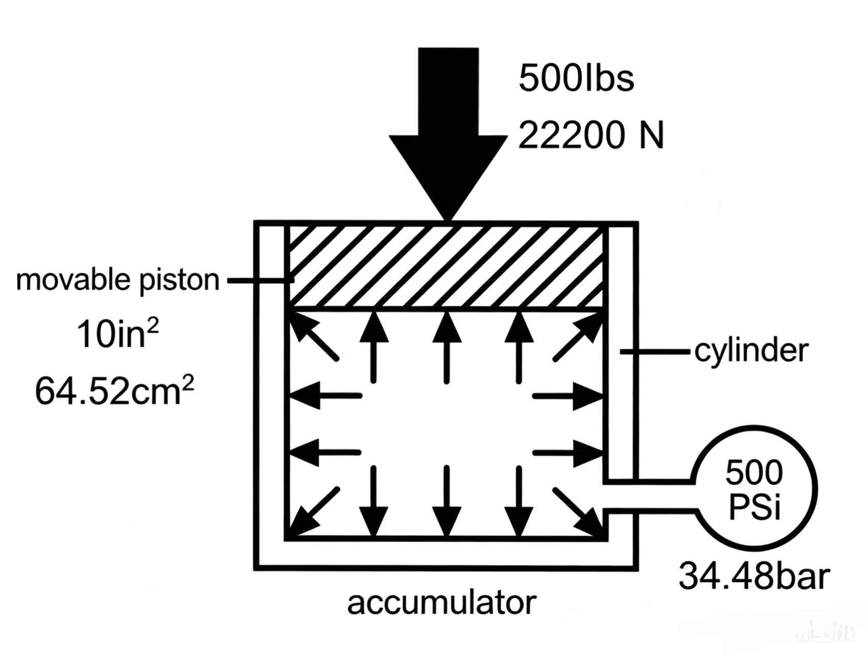
Figure 8-6 Gravity-loaded accumulator. The constant weight produces constant pressure regardless of oil volume. Used in large industrial systems such as steel mill hydraulics.
A spring-loaded accumulator uses a spring acting on a piston to maintain force on the stored oil. Spring-loaded accumulators are generally smaller than gravity types, holding a few gallons. They typically serve a single hydraulic system and usually operate at low pressure. When pressure oil enters the spring-loaded accumulator, the stored oil pressure is determined by how much the spring is compressed. When the piston moves up and compresses the spring 10 in. (25.4 cm), the stored pressure is higher than when the spring is compressed 4 in. (10.2 cm).
To prevent leaking oil from accumulating in the spring cavity, the spring cavity has a drain port for leakage to drain out. Spring-loaded accumulators should not drain externally to the reservoir, as this would cause the oil to foam. Whether the drain pipe end is above or below the reservoir fluid level, the accumulator will always produce foaming when operating — when the accumulator quickly outputs flow, the oil above the piston cannot keep up with piston movement, creating a partial vacuum in the spring cavity, causing air to separate from the oil. When the accumulator recharges, the piston moves up, pushing the air-filled oil back to the reservoir. Air bubbles in the reservoir are undesirable, so spring-loaded accumulators typically do not drain externally.
For spring-loaded accumulators with external spring cavity drain, if the piston seal wears, immediate attention is required. Without timely repair, a cleanup job may be necessary.
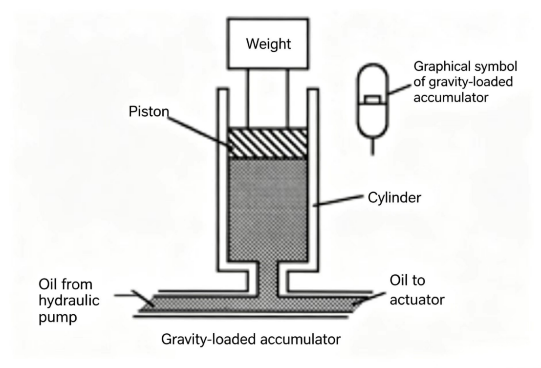
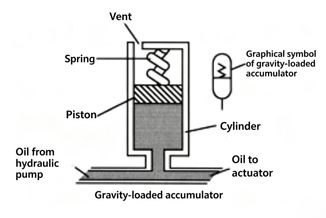
Figure 8-7 Spring-loaded accumulator. The spring force — and therefore the stored pressure — increases as the piston moves up. Used in small, low-pressure systems.
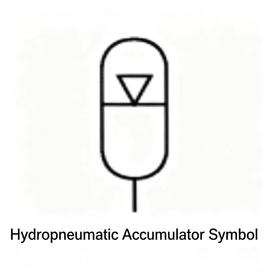
The fluid/gas accumulator is the most commonly used type in industrial hydraulic systems. It uses compressed gas to maintain working force on the stored oil.
SAFETY: In industrial systems using fluid/gas accumulators, always use dry nitrogen gas. Never use compressed air, because gas/oil vapor mixtures are explosive.
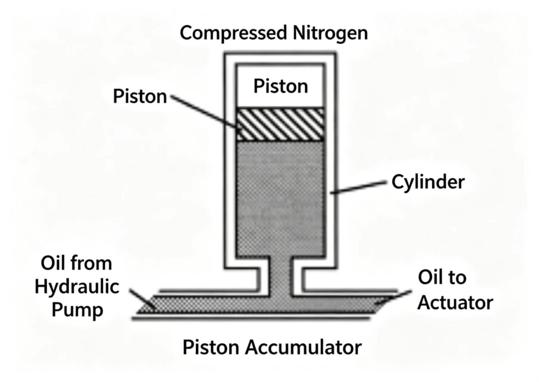
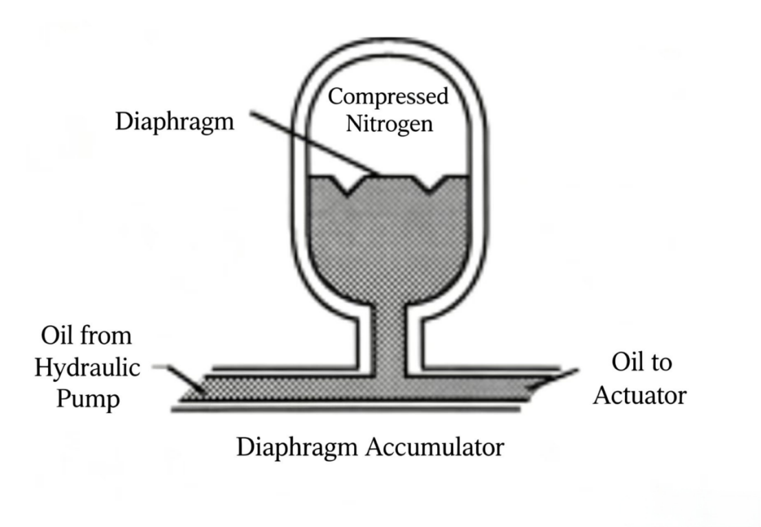
Fluid/gas accumulators are divided into piston type, diaphragm type, and bladder type, depending on the device used to separate the gas from the oil.
A piston-type accumulator consists of a barrel and a movable piston with elastic sealing rings. The upper space of the piston is filled with compressed gas. When oil is charged into the barrel, the gas is compressed. As oil is discharged from the accumulator, gas pressure drops. When all oil has been discharged, the piston reaches the end of its stroke and caps the outlet port, keeping the gas inside the accumulator.
A diaphragm-type accumulator is a sphere formed by bolting two metal hemispheres together. The internal space is divided by a synthetic rubber diaphragm — the upper chamber is filled with gas. When pressure oil enters the other chamber, the gas is compressed. Once all the oil has been discharged, the diaphragm covers the outlet port and keeps the gas in the accumulator; the diaphragm will not be pushed out beyond its thickness.
A bladder-type accumulator consists of a metal shell and an internal synthetic rubber bladder. The bladder is filled with gas. When oil enters the shell, the gas in the bladder is compressed, and oil flows out of the shell. When all oil has been discharged, gas pressure tries to push the bladder through the outlet port — but when the bladder contacts the seat valve at the outlet, the oil inside the shell is automatically sealed.
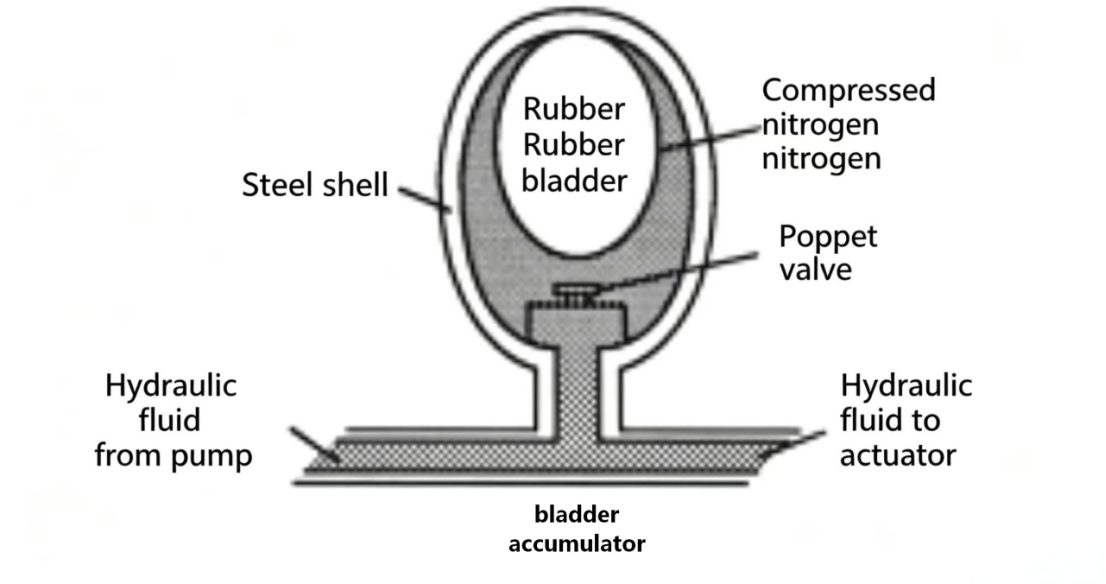
Figure 8-8 Three fluid/gas accumulator types. All use compressed nitrogen to store hydraulic energy. Piston type (top), diaphragm type (middle), and bladder type (bottom) differ in how the gas and oil are separated.
Accumulators can perform several functions in hydraulic systems: supplying flow, maintaining pressure, and absorbing shock.
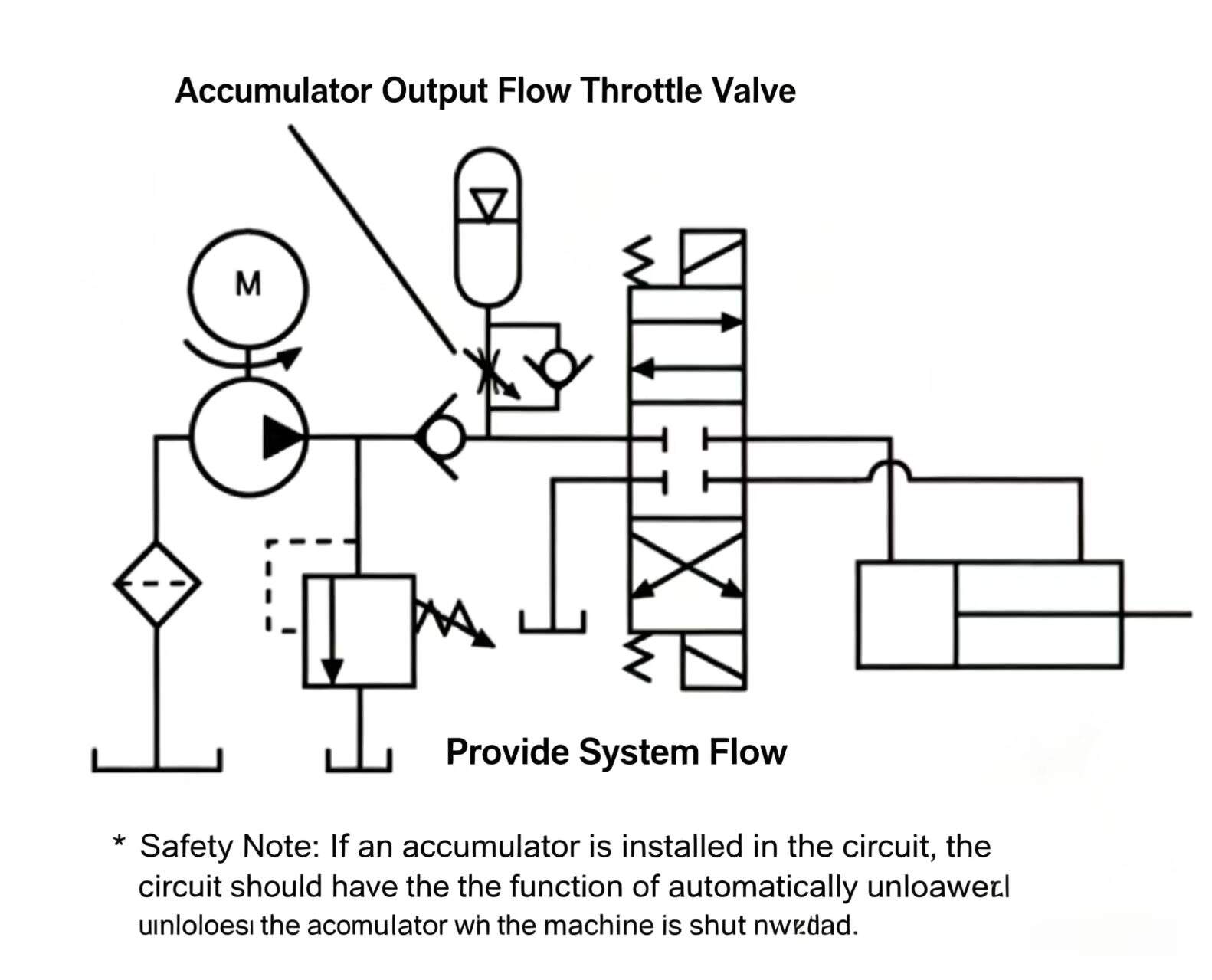
Supplying flow is one use for an accumulator. A charged accumulator is a hydraulic potential energy source. When the system requires more flow than the pump can supply, the energy stored in the accumulator can be used to generate system flow. For example, if a machine is designed so that actual working time is very short during its duty cycle, a small-displacement pump can charge the accumulator for a while. When the machine operates, the directional valve shifts to the work position and the accumulator immediately outputs pressurized oil to the actuator as required. This method of using the accumulator with a small pump stores peak power — in other words, it replaces the large flow/power of a large pump/motor in a short time with a small pump/motor averaging over a longer period.
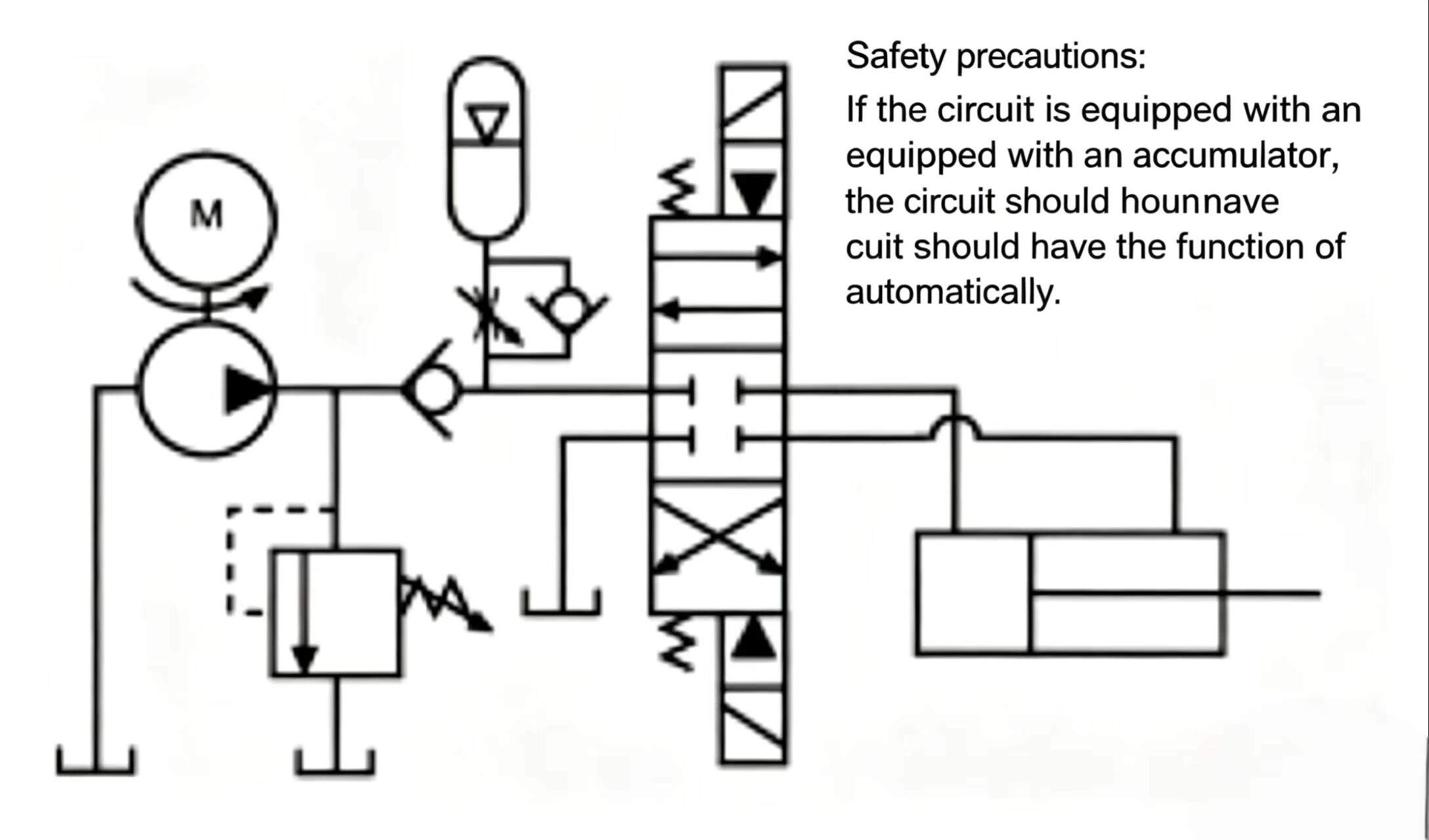
Accumulators can be used to maintain pressure. When the pump/motor is outputting flow to other parts of the system, an accumulator can maintain pressure on one branch of the circuit.
When the system requires clamp cylinder A to return, clamp cylinder B must maintain pressure. As directional valve A shifts, the pressure in the hydraulic pump and A cylinder lines drops quickly, while B cylinder is maintained by the accumulator, which has already stored enough pressure oil to compensate for the leakage in B cylinder lines.
In another application, a working cylinder near a furnace experiences high ambient temperature that causes the oil to expand thermally. The accumulator absorbs the increased volume and maintains the pressure at a relatively constant level. Without the accumulator, pressure rise in the lines would be uncontrolled and could cause component housing, pipe, or fitting rupture.
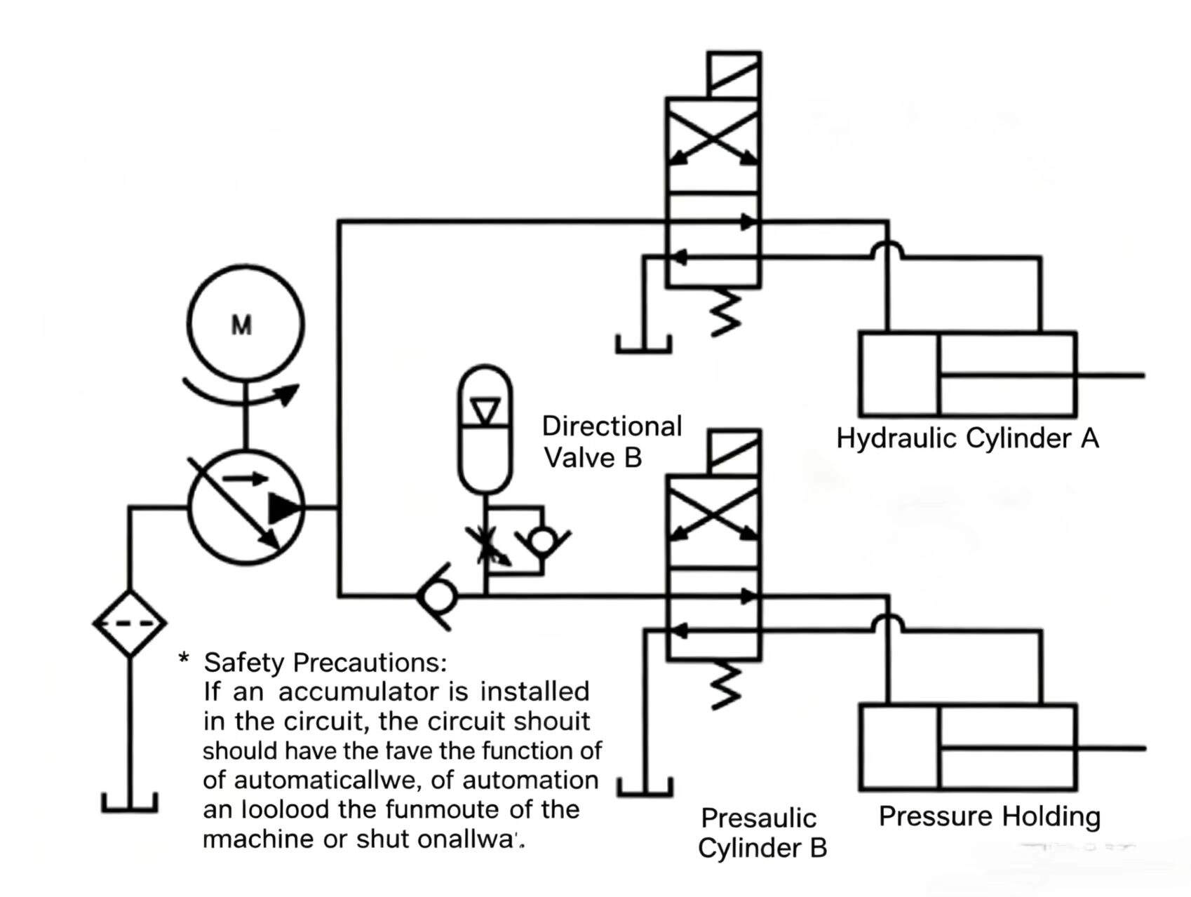
Figure 8-10 Accumulator for pressure maintenance. (Top) Maintains pressure on one circuit branch while the pump serves another. (Bottom) Absorbs volume changes from thermal oil expansion near heat sources.
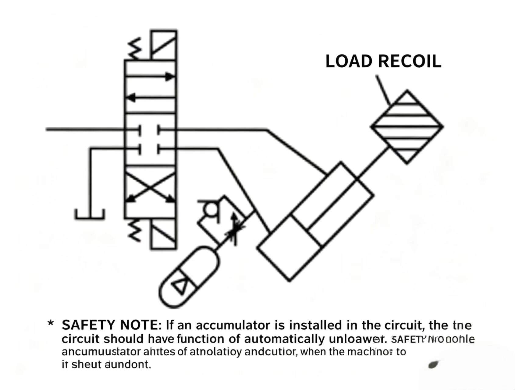
Fluid/gas accumulators can also be used to absorb system shock. Shock in a hydraulic system can be caused by the inertia of a load connected to a cylinder or motor, or by sudden flow cutoff or rapid directional valve switching, which creates shock from fluid inertia. An accumulator in the circuit can absorb part of the shock and prevent it from spreading throughout the system.
External mechanical forces can also create hydraulic shock. A load connected to a hydraulic cylinder with rebound tendency pushes the piston back, creating hydraulic shock. An accumulator in the cylinder line, if correctly charged, helps reduce the shock effect. If incorrectly charged, it can also cause overpressure.
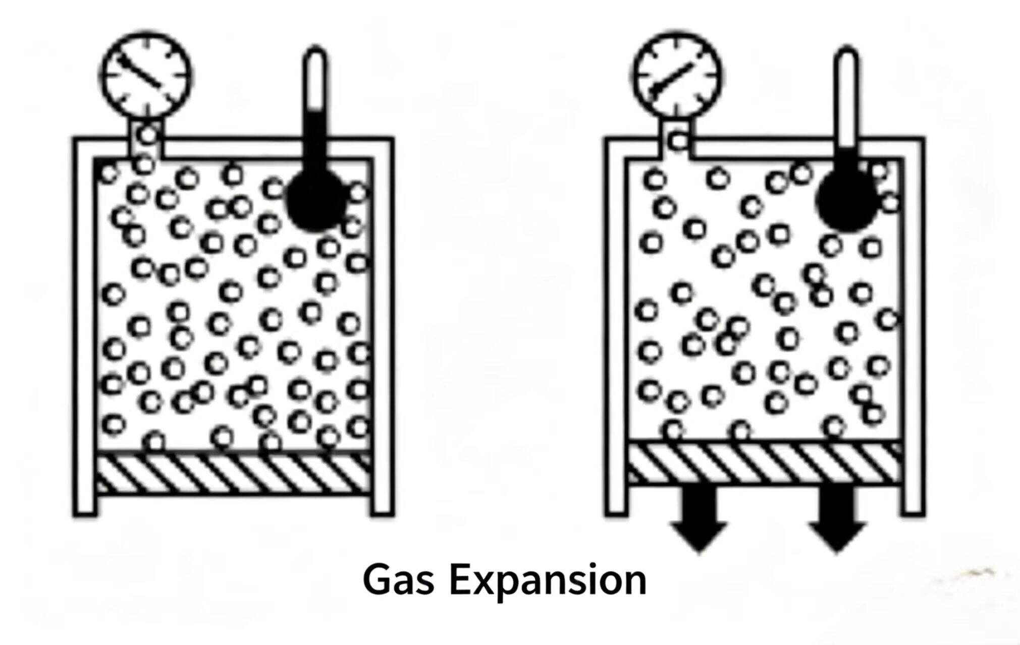
Since fluid/gas accumulators use compressed gas to store oil pressure, gas properties affect accumulator performance. When a fluid/gas accumulator is charged, the gas is compressed and its temperature rises. At constant pressure, hot gas occupies more space than cooler gas.
The isothermal process describes the accumulator operating state when gas temperature is held constant. During charging, isothermal operation means the gas is compressed slowly enough that all the heat generated by compression is fully dissipated. The adiabatic process describes the accumulator operating state when gas temperature changes. During charging, adiabatic means the gas is compressed so quickly that all the heat is retained.
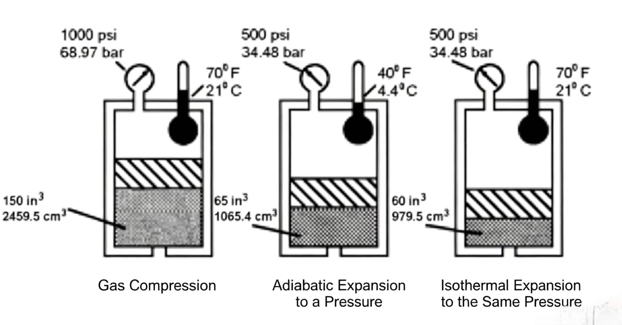
For a fluid/gas accumulator charged to the same pressure, the isothermal process stores more oil than the adiabatic process.
Numerical example: A piston accumulator initially has gas pressure 500 psi (34.48 bar) and temperature 70°F (21°C). If charged to 1,000 psi (68.97 bar) by adiabatic process (fast), temperature and pressure rise together. At 1,000 psi (68.97 bar) the oil stops entering; temperature is 150°F (65.6°C) and the accumulator stores 135 in³ (2,215.65 cm³) of oil. If charged isothermally (slow), temperature stays at 70°F (21°C) throughout; at 1,000 psi (68.97 bar) the oil stops and the accumulator stores 150 in³ (2,458.5 cm³) of oil.
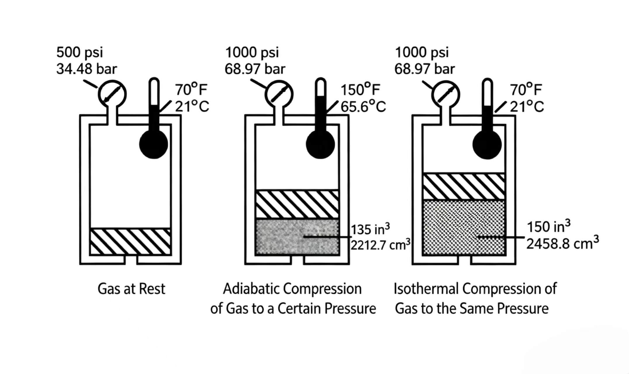
Figure 8-12 Isothermal vs adiabatic charging. Slow (isothermal) charging stores more oil than fast (adiabatic) charging at the same final pressure, because temperature stays lower and gas occupies less space.
During oil discharge, gas expands and cools. At constant pressure, cooler gas occupies less space than warmer gas. In practice, accumulator operation is generally adiabatic — not isothermal. In the following sections, the primary concern is not how much oil the accumulator can store, but rather how much oil it outputs before pressure drops to a lower level, which is heavily influenced by the precharge pressure.
When an accumulator is completely empty of oil, the gas pressure charged into the fluid/gas accumulator is the precharge pressure. This pressure significantly affects the effective volume and shock-absorbing performance of the accumulator.
Fluid/gas accumulators used to produce system flow or maintain pressure typically operate between maximum and minimum working pressures. When fully charged with oil, the accumulator reaches maximum working pressure. When needed, working pressure drops, the accumulator outputs oil, down to a lower minimum pressure. The oil volume the accumulator outputs between maximum and minimum working pressures is the effective volume.
Precharge pressure affects the effective volume. Example: a 231 in³ (3,786 cm³) fluid/gas accumulator in a system uses a small pump to charge oil up to system pressure of 2,000 psi (137.9 bar). To supply flow, pressure is allowed to drop to 1,500 psi (103.4 bar). The chosen precharge pressure determines how much oil the accumulator provides to the system.
From the performance table, a 231 in³ (3,786 cm³) accumulator with 100 psi (6.89 bar) precharge can store 210 in³ (3,441.9 cm³) of oil at 1,000 psi isothermal charge (upper limit = isothermal values). At 1,500 psi (103.4 bar) it stores 202 in³ (3,310.8 cm³), delivering 8 in³ (131 cm³) between the two pressures. This low precharge accumulator stores a lot of oil but delivers very little.
Increasing precharge to 1,000 psi (68.96 bar), the accumulator stores 93 in³ (1,524.3 cm³) at 2,000 psi (137.9 bar) and 59.5 in³ (975 cm³) at 1,500 psi (103.4 bar), delivering 33.5 in³ (594.1 cm³). The higher precharge stores less oil but delivers much more. With 1,400 psi (96.6 bar) precharge, stored oil is minimum but delivered oil is maximum.
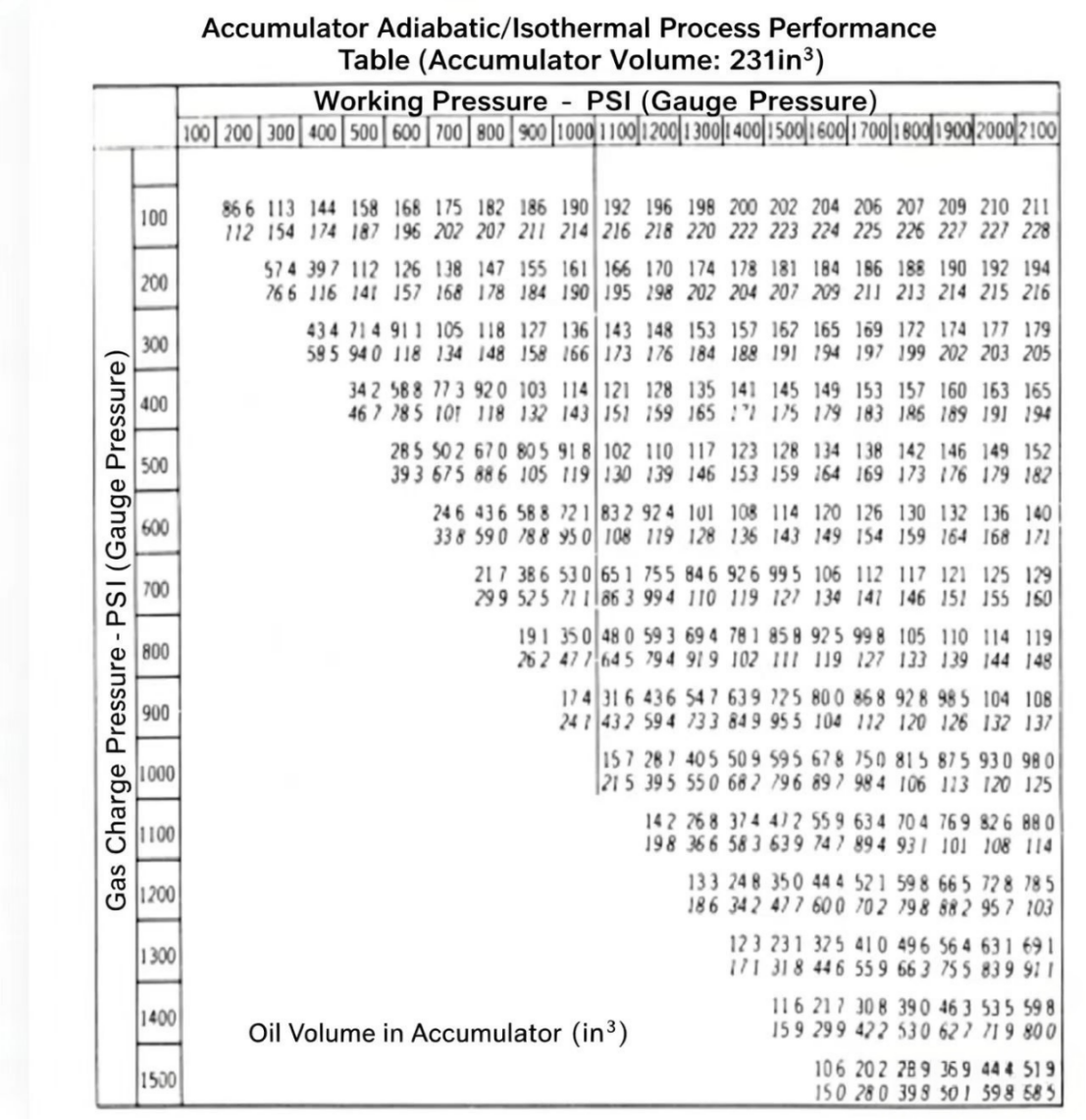
Figure 8-13 Accumulator performance table (231 in³ capacity). Higher precharge pressure delivers more oil per cycle between given pressure limits, but stores less total oil. Select precharge based on required effective volume, not total capacity.
The effective volume output of an accumulator should be controlled by the flow. For pressure maintenance, the controlled flow is determined by the leakage that needs compensating. For accumulators used to supply pressure oil, when the downstream directional valve shifts, the effective volume output is too fast. For this reason, these accumulators often have flow control valves and bypass check valves on their inlet/outlet ports.
When a fluid/gas accumulator is used as a shock absorber, its precharge is generally set slightly above the maximum working pressure in the circuit (set at approximately 100 psi / 6.896 bar above the maximum by the relief valve setting). If the maximum working pressure is set by the relief valve, the precharge can be set approximately 100 psi above the relief valve setting.
The precharge pressure of a fluid/gas accumulator affects its shock absorption capability. In a hydraulic system, shock is caused by external mechanical forces on a cylinder or motor causing a rapid pressure rise, or by the fluid's inertia when a hydraulic valve suddenly closes.
The accumulator can absorb the portion of shock-pressure oil it can compress and transfer. A line with an accumulator becomes compressible above a certain pressure. If the accumulator precharge is too low, it already stores some oil before the shock arrives, so it can only absorb 4 in³ (65.6 cm³). If precharge is 2,500 psi (172.4 bar) — too high — pressure rises to nearly 2,800 psi (193 bar) before absorbing 4 in³. For shock absorbers, precharge pressure is extremely important.
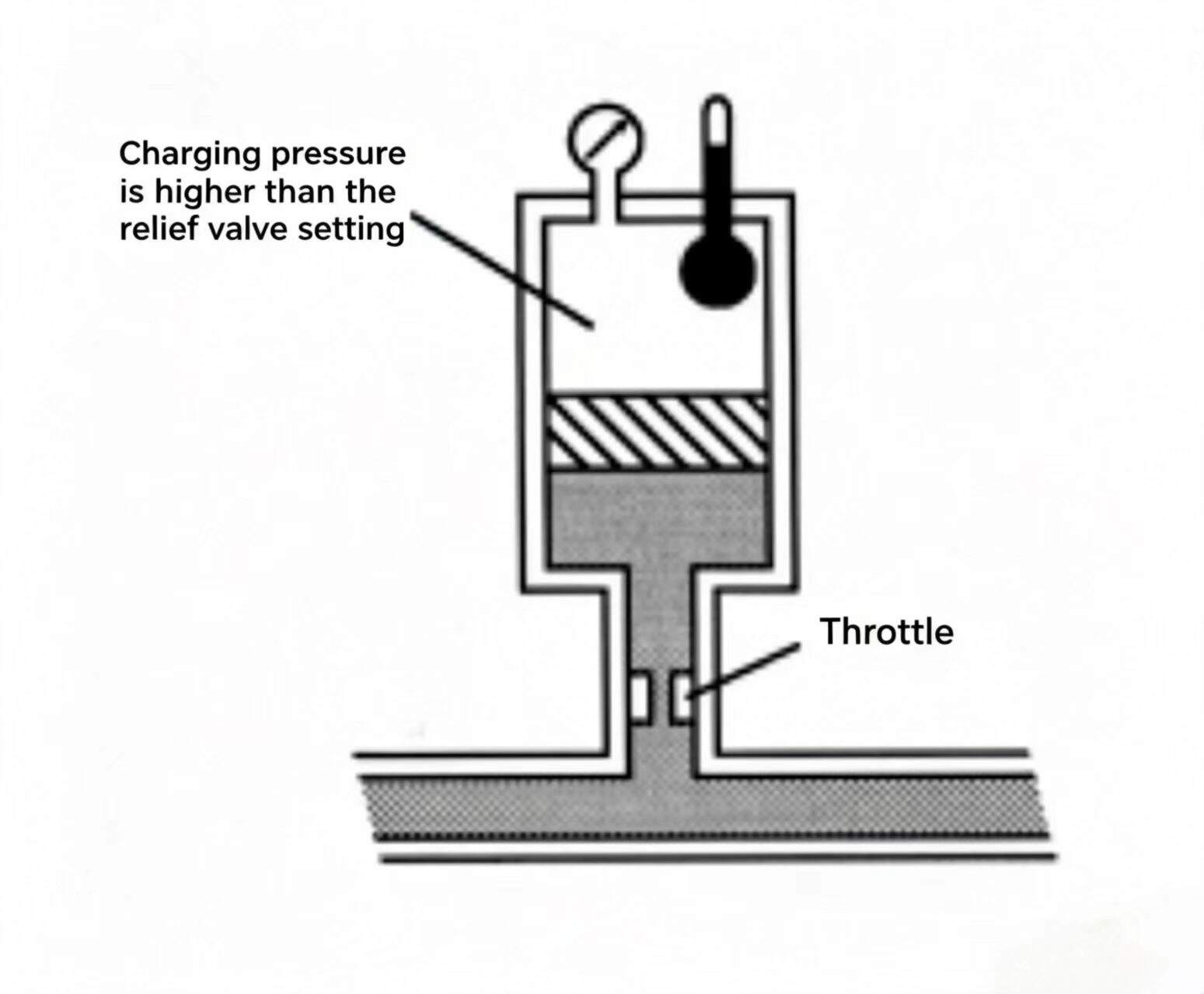
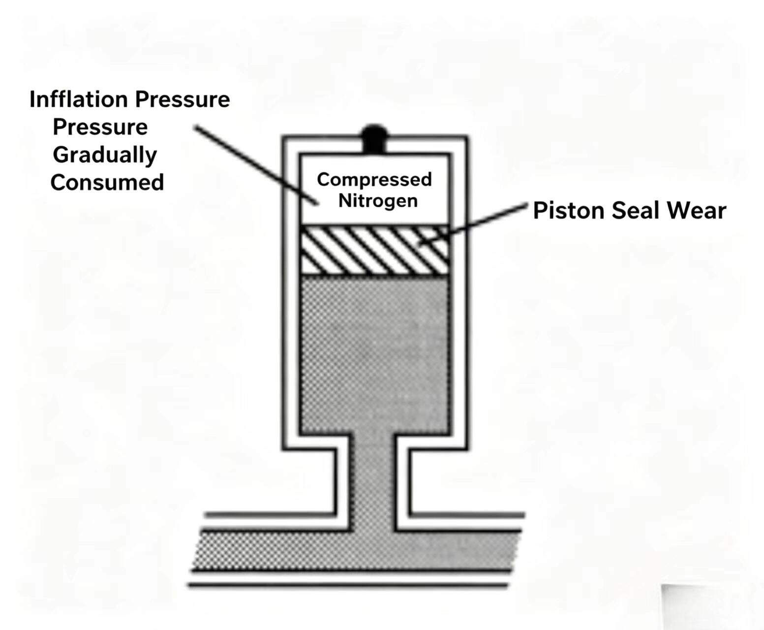
A fluid/gas accumulator is charged with gas to the appropriate precharge pressure once. This means the same precharge cannot be maintained indefinitely. When the accumulator operates, compressed gas leaks through the gas valve — possibly due to gas valve failure or poor sealing, or a problem with the tapered valve core seating in the valve seat. Gas pressure also decreases gradually during oil discharge for bladder and diaphragm accumulators — this typically occurs catastrophically, causing the synthetic rubber diaphragm material to break. For piston accumulators, during the discharge process, charged gas can escape past worn seals, from the piston area. Gradual loss of precharge can indicate a piston-type accumulator with some degree of wear.
Correct precharge pressure is critical for fluid/gas accumulator performance, so it should be checked regularly. A charging device with a pressure gauge is needed to check precharge pressure. The device mainly consists of a charging chuck, bleed valve, and pressure gauge.
Procedure to check: discharge all oil from the accumulator, remove the protective cap (usually on the gas valve at the top). With the chuck handle fully withdrawn, check that the bleed valve is closed. Connect the charging chuck to the accumulator gas valve, tighten the chuck wing nut, ensure a reliable connection to the gas valve. Thread in the chuck screw to fully press the accumulator gas valve core; read the gauge pressure — this is the accumulator precharge pressure.
If precharge is correct, rotate the chuck handle out to close the accumulator gas valve, open the bleed valve to depressurize the charging device, loosen the chuck wing nut, remove the device from the accumulator, reinstall the gas valve protective cap.
If precharge is too high, open the bleed valve to release excess pressure. If precharge needs to be increased, first withdraw the chuck handle to close the accumulator gas valve, open the bleed valve to depressurize the charging device, then close the bleed valve, connect the charging device to a nitrogen cylinder. Rotate the chuck handle in to fully press the accumulator gas valve core, open the nitrogen cylinder valve to let gas slowly enter the accumulator. When the gauge shows the desired pressure, close the gas valve. Once the gauge shows the correct precharge, close the nitrogen cylinder valve, withdraw the chuck handle to close the accumulator gas valve, open the bleed valve, then disconnect the flexible charging tube and charging device.
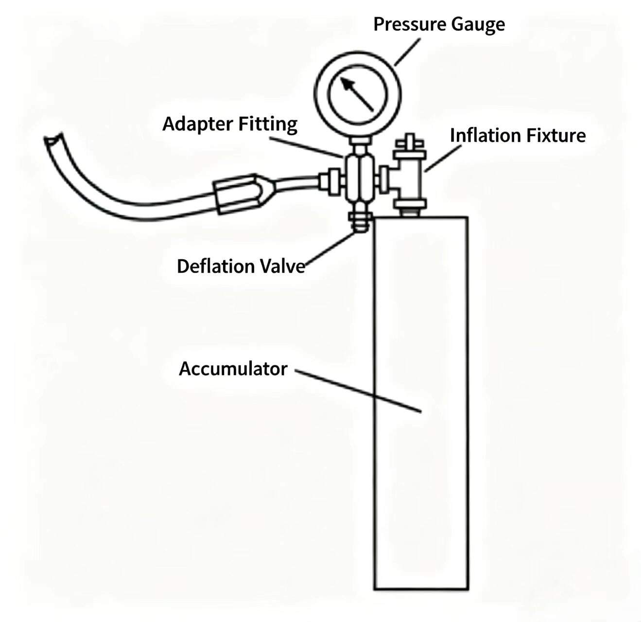
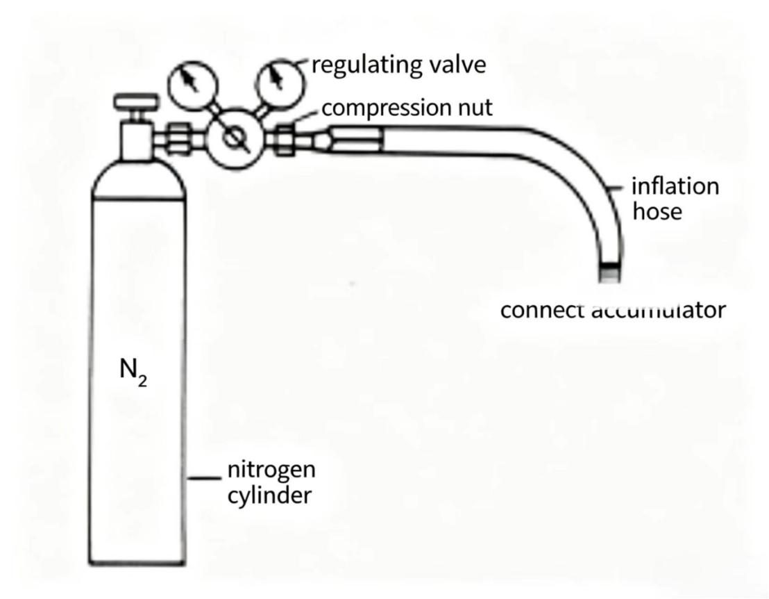
Figure 8-15 Checking and setting accumulator precharge. (Top) Worn piston seals cause gradual precharge loss. (Bottom) Standard nitrogen charging kit — always use dry nitrogen, never compressed air.
In a typical hydraulic circuit with an accumulator, when the accumulator is fully charged and no part of the system is working, the pump/motor flow should be unloaded to the reservoir at as low a pressure as possible. In the circuit shown, a dump valve is used for unloading. Once the accumulator charges to the dump valve setting, the dump valve opens and routes pump flow to the reservoir.
Typically this type of unloading can only last a few seconds, because there is always some leakage downstream of the check valve. The accumulator must compensate for this leakage — pressure gradually drops — the dump valve gradually closes, and the opening to the reservoir gets smaller and smaller, until the accumulator pressure drops below the valve opening pressure. As the valve closes, the pump/motor must build more power to recharge the accumulator to the dump valve setting.
To ensure the pump/motor is completely unloaded before recharging the accumulator, a pressure switch can be used. In the circuit, the pressure switch senses accumulator pressure and sends an electrical switching signal at a set pressure point. The electrical signal goes to a normally closed two-way solenoid valve — this solenoid valve can control a pilot-operated relief valve to unload. When the accumulator charges to the pressure switch setting, the relay sends a signal to the solenoid valve to unload the relief valve and route pump/motor flow to the reservoir through the relief valve.
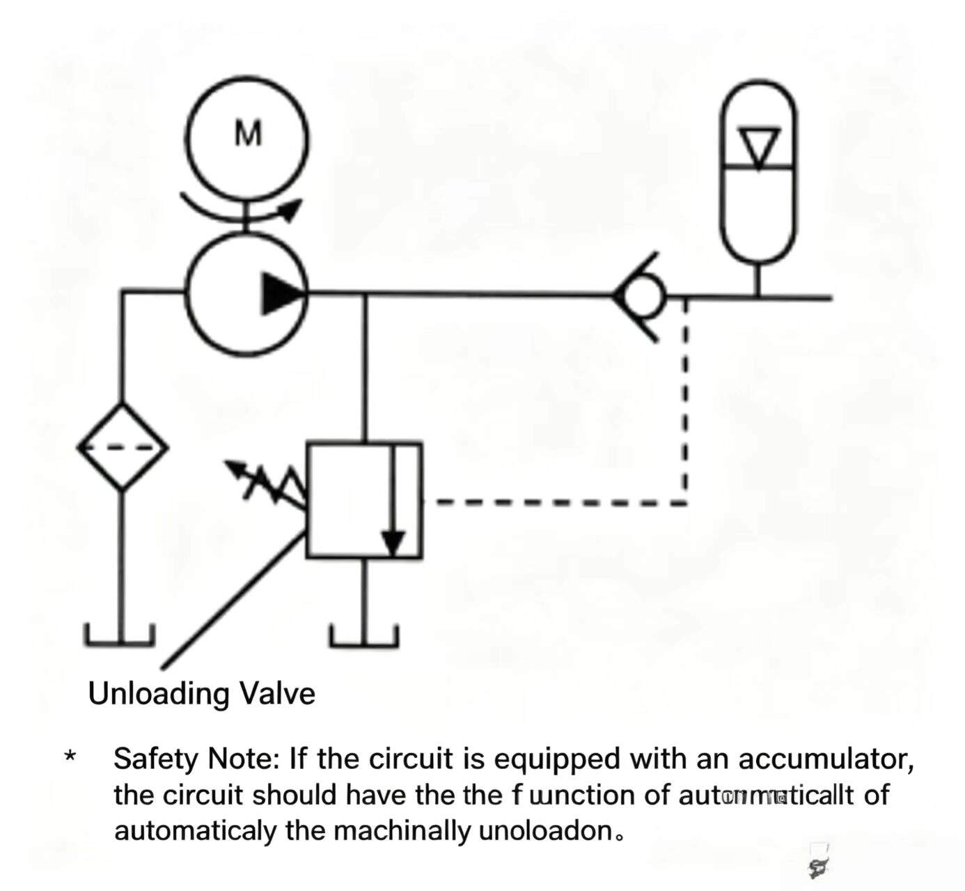
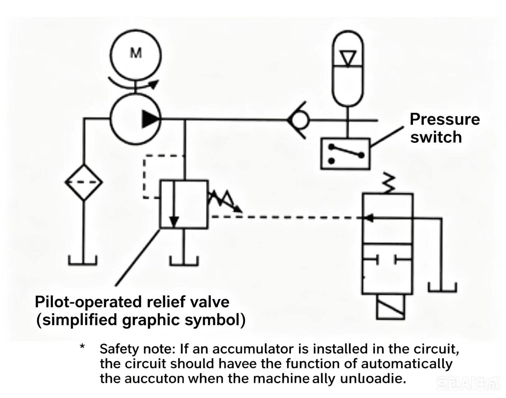
Figure 8-16 Accumulator unloading circuits. (Top) Simple dump valve — unloads to tank when accumulator reaches set pressure, but tends to cycle. (Bottom) Pressure switch with pilot relief valve — ensures full unloading and precise pressure band control.
After the accumulator has been charged, a differential-pressure unloading valve can replace the pressure switch and solenoid valve to release the relief valve and unload the pump/motor. The differential-pressure unloading valve is a hydraulic valve designed specifically for accumulator applications. As its name implies, this valve uses a pressure differential to unload the pump/motor.
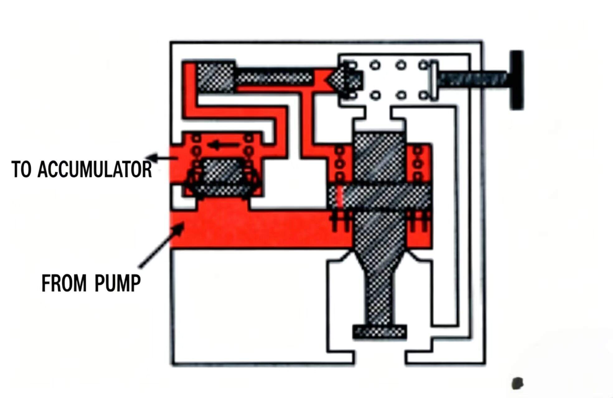
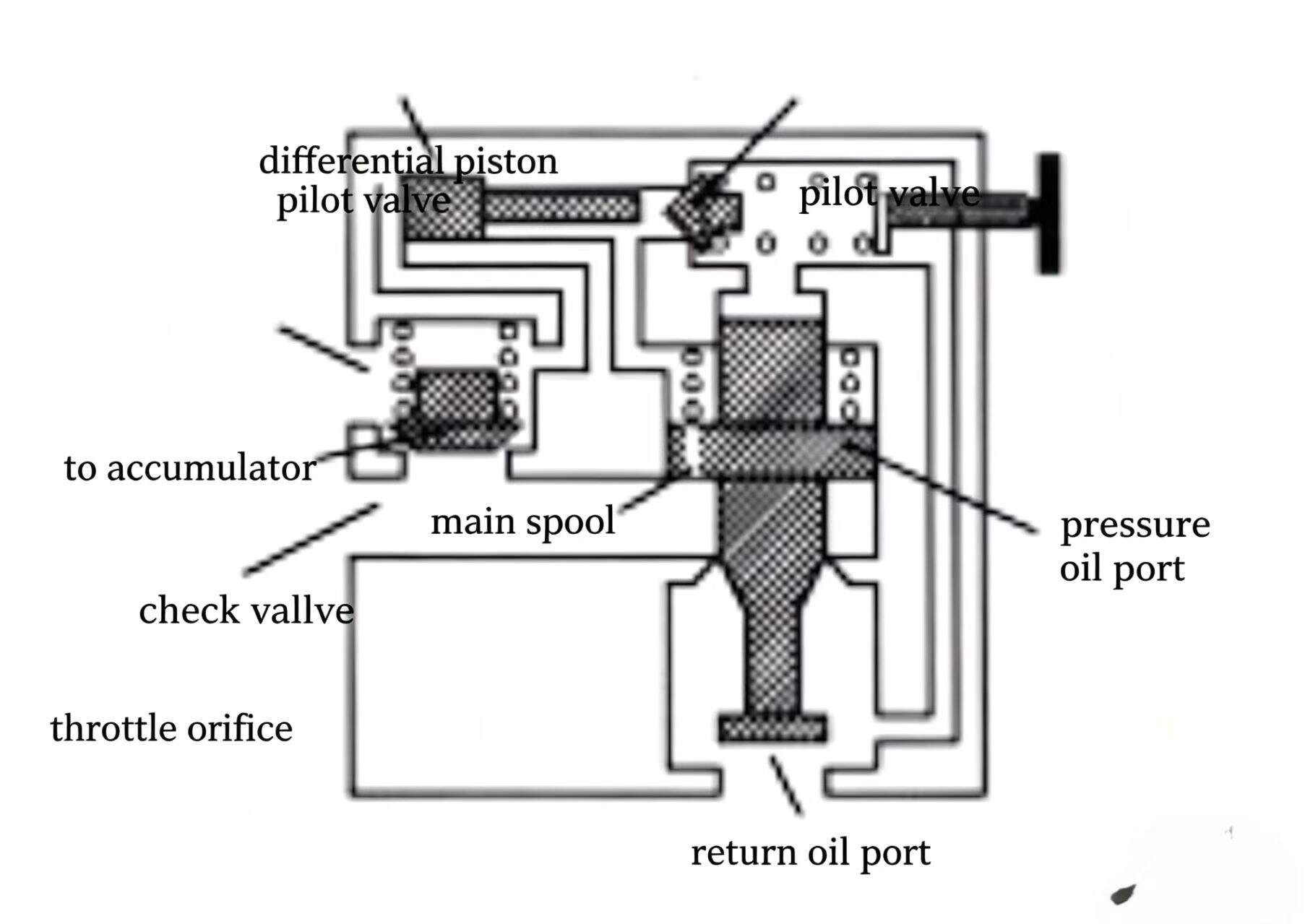
The differential-pressure unloading valve is assembled from a pilot-operated relief valve, a check valve, and a differential piston in one valve body. The valve body has three ports: pressure port, return port, and accumulator port.
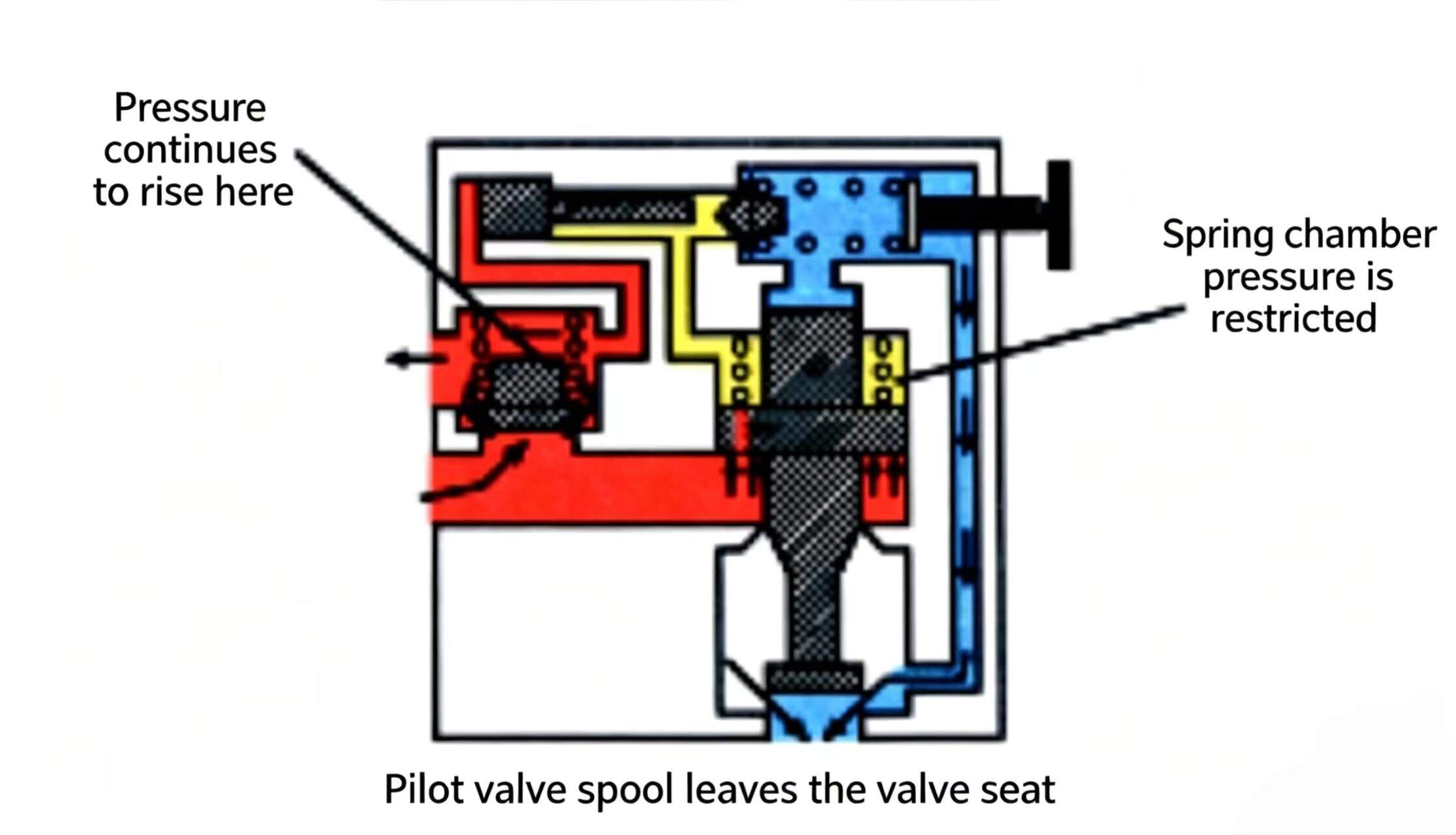
Inside the differential-pressure unloading valve, the check valve and pilot-operated relief valve operate normally. Pump output oil can charge the accumulator through the check valve. The differential piston sits opposite the pilot relief valve spool and can move freely in its bore. The piston's two ends are exposed to equal areas of pressure. When the accumulator is being charged, pressure on both sides of the piston is nearly equal (ignoring the pressure drop through the check valve), so the piston doesn't move. When the pressure on the pilot valve spool is large enough, the pilot spool is pushed off its seat — as already known, this pilot movement can restrict the pressure in the main valve spring cavity. Because the main valve spring cavity and one end of the differential piston are pressure-restricted, the piston moves toward the pilot valve spool, pushing the pilot spool completely off its seat, effectively releasing the control pressure on the main spool spring cavity, unloading the relief valve, unloading the pump/motor. The check valve simultaneously closes so accumulator oil cannot be discharged through the relief valve.
The differential piston area exposed to pressure is 15% larger than the pilot valve spool area. Since force = pressure × area, the force keeping the pilot spool off its seat is 15% greater than the force lifting the pilot spool. This means the spring must get force greater than 15% from somewhere else to re-seat the pilot spool — or the system pressure must drop 15% before the pilot spool can re-seat.
This ensures the differential-pressure unloading valve maintains the pump/motor in unloaded state after accumulator charging until pressure drops by a fixed percentage — generally about 15% of the pilot valve setting. For example, with the pilot valve set at 1,000 psi (69 bar), unloading occurs between 1,000 psi (69 bar) and 850 psi (59 bar); with the pilot valve at 2,000 psi (138 bar), unloading range is 2,000 psi (138 bar) to 1,700 psi (117 bar).
In any application, for hydraulic work energy to do useful work, it must be converted to mechanical energy. Hydraulic cylinders convert hydraulic energy into linear mechanical motion.
A hydraulic cylinder consists of a barrel, a movable piston with flexible sealing rings connected to a piston rod, and two end caps. The end caps can be threaded, flanged, drawn-over, or welded onto the barrel. Industrial hydraulic cylinders commonly use bolted rod-end connections. When the piston rod moves, it is known as a piston rod seal kit or a detachable guide ring that guides and supports the piston rod.
The end with the piston rod is called the "rod end"; the other end without a rod is called the "blind end." The inlet and outlet ports are located on the rod-end and blind-end caps.
For proper operation, the piston and piston rod guide seal of the hydraulic cylinder must have reliable seals. Common seals used in hydraulic cylinder pistons are lip seals, cast iron piston rings, or single double-direction seal units. Seal materials and components should be confirmed to be compatible with the working fluid and operating conditions.
The piston rod multi-layer seal is an effective piston rod seal type, consisting of a main seal with a lip-shaped inner seal surface, a wiper that continually contacts the piston rod surface during operation, and scrapes the working oil from the piston rod surface. The secondary dust seal collects the residual oil left by the main seal, and during piston rod retraction, wipes off any foreign matter clinging to the piston rod.
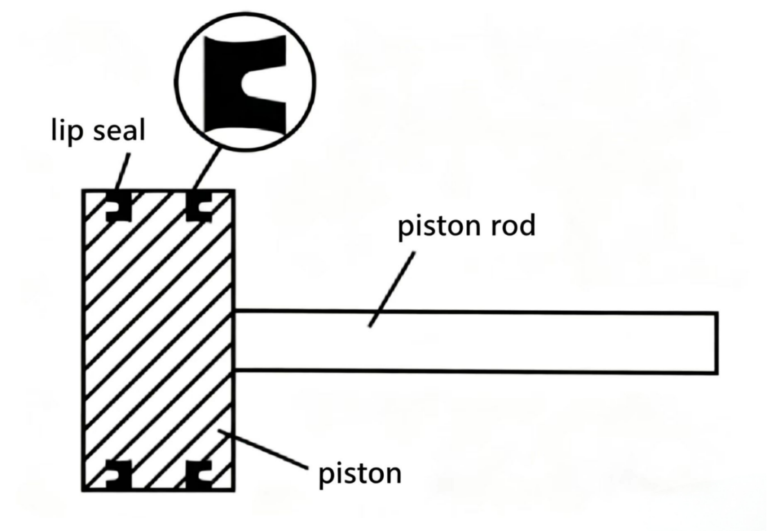
As described above, oil accumulated in the cavity between the main seal and dust seal can return to the cylinder bore during the retraction stroke — this is normal. However, if the cylinder stroke is particularly long (10 ft / 3.05 m or longer), the oil accumulated in the seal cavity could be enough to exceed the piston rod seal capacity. In this situation and when there is excess oil in the seal cavity, the piston rod seal cavity should have an external drain connection.
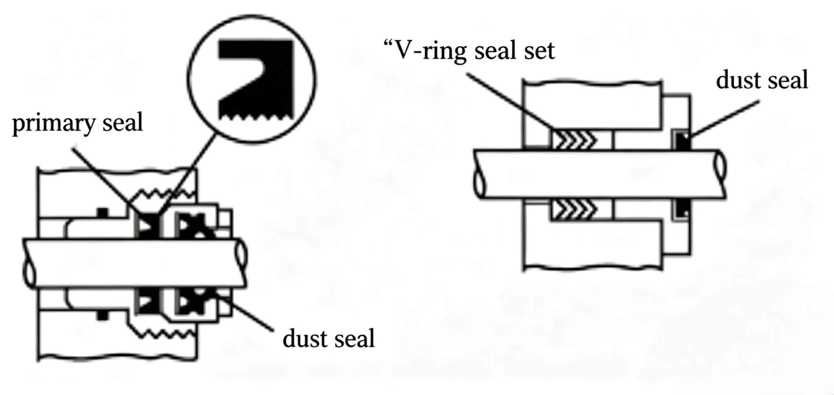
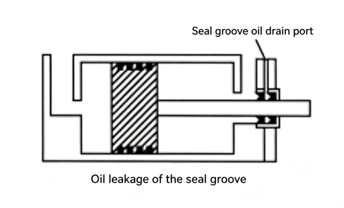
Figure 8-18 Cylinder construction details. The rod-end cap contains the piston rod seal assembly. For long-stroke cylinders, a drain port is added to prevent oil from overwhelming the seal.
When hydraulic energy drives the cylinder piston to the end of stroke (the end of cylinder travel), oil's inertia becomes shock — the so-called "hydraulic shock." If the energy is large enough, this shock can damage hydraulic cylinders.
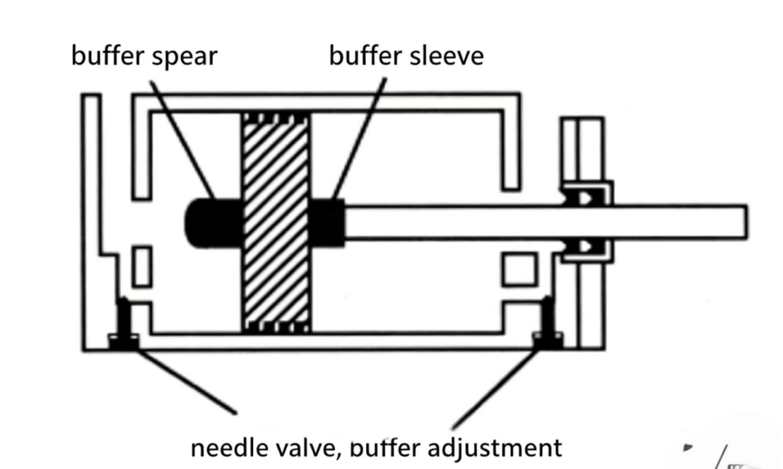
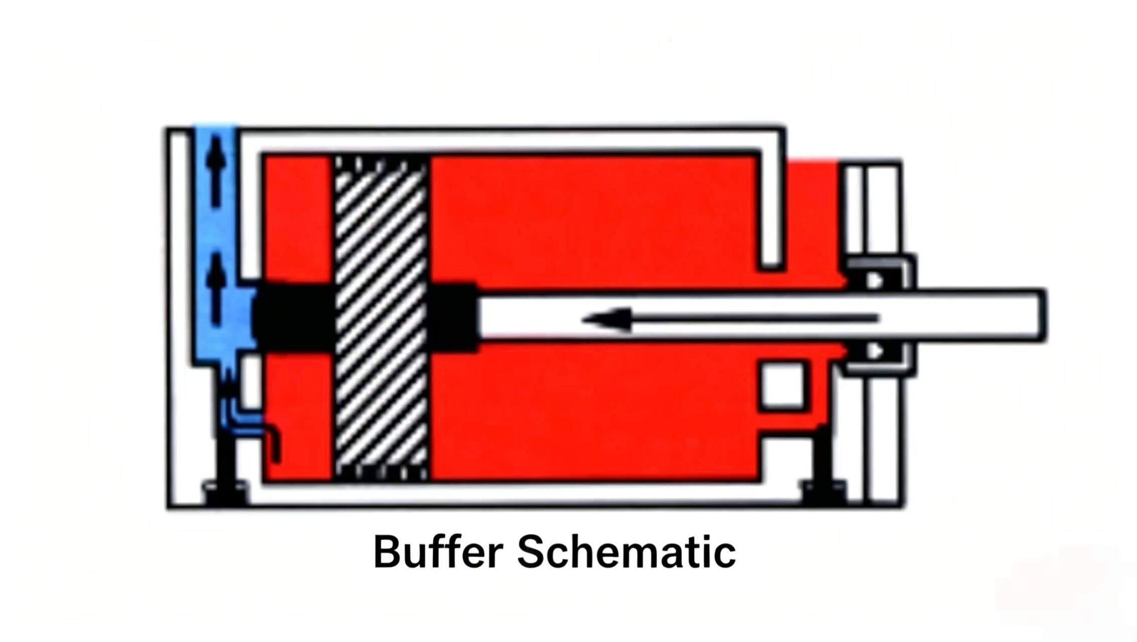
To protect hydraulic cylinders from excessive shock, cushion devices can be installed. Cushion devices can decelerate the cylinder piston near the end of stroke. Cushion devices can be installed on either end or both ends of a hydraulic cylinder.

A cushion device consists of a flow-controlling needle valve and a cushion spear installed on the blind end of the piston, and a cushion sleeve on the piston rod. These devices act as plugs at each end.
As the hydraulic cylinder piston approaches the stroke end, the cushion spear or cushion sleeve blocks the normal oil outlet. This forces the oil to flow through the needle valve only. Part of the pressure oil at the relief valve setting escapes through the needle valve. The remaining flow through the needle valve determines the cylinder's deceleration rate. Needle valve adjustment determines the deceleration rate of the piston. On the return stroke, flow enters the cylinder through a single check valve (not shown) to bypass the needle valve, so reverse speed is unaffected.
Sometimes the stroke length of a hydraulic cylinder must be limited by external control. By installing a stop screw that can be screwed in and out on the barrel, the stroke can be pre-adjusted. Any type of stroke adjuster must be verified against requirements for stopping force, collision, impact, and dimensional effects.
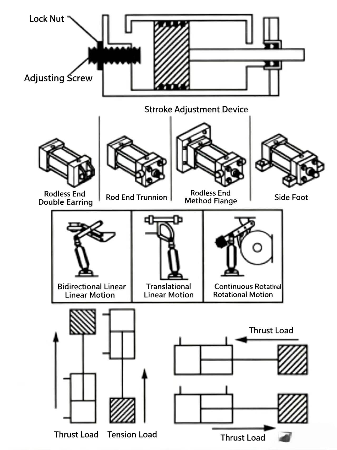
Figure 8-19 Cylinder cushions, stroke adjusters, mounting styles, and load types. Cushions protect the cylinder at end of stroke; mounting style determines how well the cylinder can handle its load.
Hydraulic cylinders have many mounting styles, including: flanges, trunnions, side-lug mounts, centerline screws, double lug rings, tie-rods, and weld mounts. Center-lug mounts or weld mounts are a very good design since they produce minimum cylinder-operation misalignment.
Hydraulic cylinders can convert hydraulic energy to straight-line or linear mechanical motion. However, due to the selection of mechanical linkages, cylinders can also provide many different types of mechanical motion.
Hydraulic cylinders can move many different types of loads in numerous applications. In general, loads pushed by the piston rod are called push loads; loads pulled by the piston rod are called pull loads.
A stop tube is a solid metal sleeve mounted on the piston rod. When a long-stroke cylinder's piston rod is fully extended, the stop tube separates the piston and guide sleeve by a distance. The piston rod guide sleeve is a bearing that supports the piston rod during cylinder operation. It is designed to bear a certain load. The piston rod guide sleeve — in addition to being a shaft — is also a load point for the piston rod. For long-stroke cylinders connected to loads, the piston rod without a rigid guide will tend to droop when fully extended, or bending may occur at the guide sleeve, adding side load that damages the piston rod guide sleeve.
The stop tube function is to separate the piston and guide sleeve by a distance when the piston rod is fully extended, reducing the load on the piston rod guide sleeve.
Hydraulic cylinders come in many types. Below are some commonly used cylinder types; they will also appear in certain application circuits in later lessons.
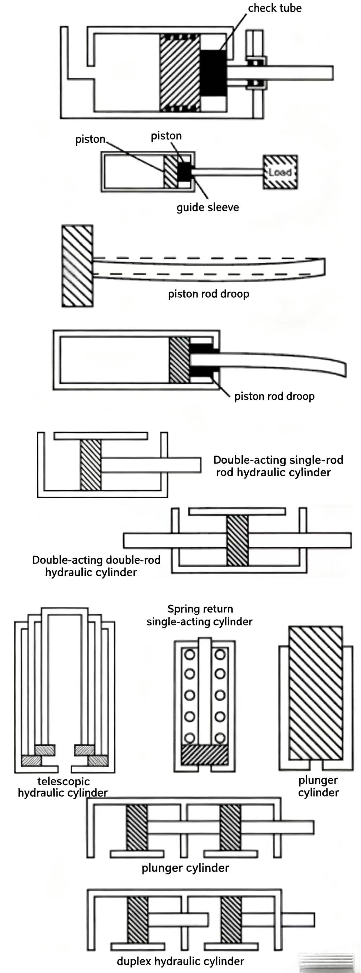
Figure 8-20 Hydraulic cylinder types. Each type is suited to a specific application: telescoping for long stroke in limited space, tandem for high force in limited bore diameter, double-rod for equal force/speed in both directions.
The most common type in industrial hydraulics is the double-acting single-rod cylinder. For this type, key concerns are the allowable gpm and psi, and the converted mechanical force and piston rod motion.
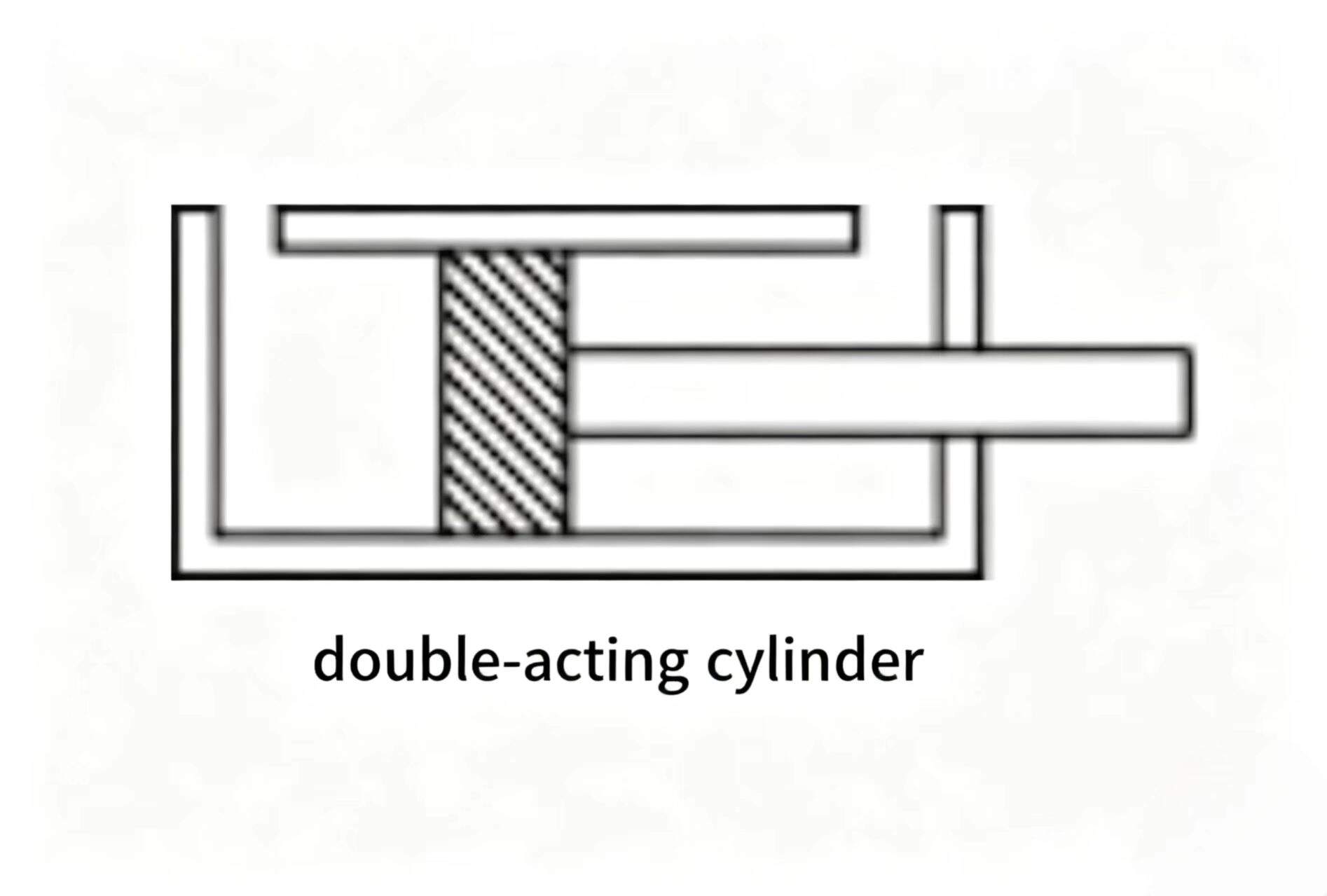
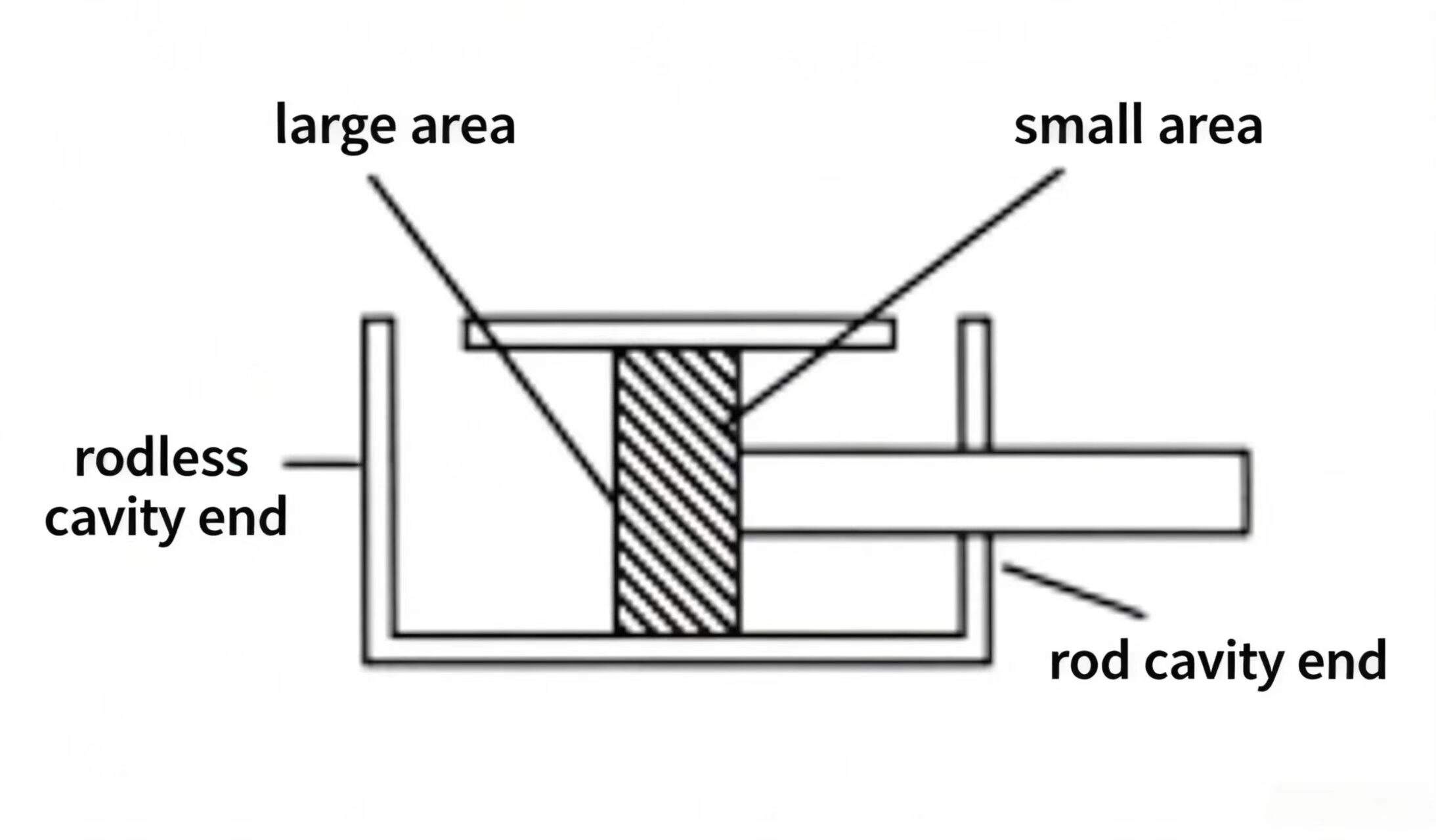
Piston area and effective piston area are generally discussed for double-acting single-rod cylinders. The large piston area is the full piston cross-section area exposed to pressure in the cylinder blind end (rod-free side). The effective small area (annular area) is the piston area exposed to pressure on the rod side, because the piston rod takes up part of the piston area. Therefore, the effective small area is generally less than the large area.
The hydraulic cylinder piston rod extension speed is determined by how fast the fluid fills the cylinder blind end. Piston rod speed is commonly expressed in ft/min or m/min:
Rod speed (ft/min) = Flow rate (gpm) x 19.25 / Piston area (in^2)
*Rod speed (m/s) = Flow rate (Lpm) x 0.167 / Piston area (cm^2)
* If calculating in m/s and the result is less than 0.1 m/s, express the result in mm/s.
Example: a cylinder with piston area 10 in² (64.5 cm²) receives 5 gpm (18.95 lpm) flow. Rod speed = (5 × 19.25) / 10 = 9.63 ft/min (49 mm/s). With double the flow (10 gpm / 37.9 lpm), rod speed doubles to 19.25 ft/min (97.33 mm/s).
During piston rod retraction, flow enters the rod end. At the same input flow rate, retraction speed is faster than extension speed — use the small (annular) piston area in the formula.
Example: 10 gpm (38 l/min) flow enters the rod end of a cylinder with 10 in² (65 cm²) large area and 8 in² (52 cm²) small area. Retraction speed = (10 × 19.25) / 8 = 24.06 ft/min (0.12 m/s).
Rod speed (ft/min) = Flow rate (gpm) x 19.25 / Small area (in^2)
Rod speed (m/s) = Flow rate (Lpm) x 0.167 / Small area (cm^2)
With the same input flow rate, a double-acting single-rod cylinder retracts faster than it extends.
During retraction, flow enters the rod end and exits the blind end. The discharge flow is greater than the input flow — it can be calculated with the same formula as gpm (l/min) but using the large piston area. Example: 10 gpm entering rod end at speed 24.06 ft/min: outflow = (24.06 × 10) / 19.25 = 12.5 gpm (46 L/min).
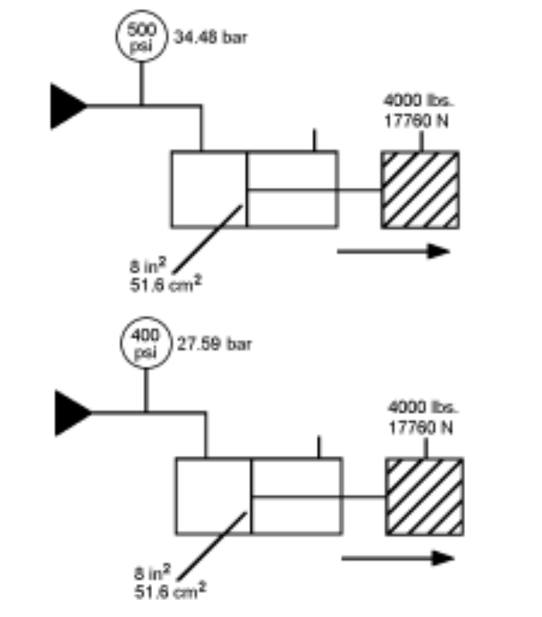
As shown, the force produced by a hydraulic cylinder is a function of hydraulic pressure acting on the cylinder piston area. If a specific cylinder needs to produce more than the current maximum output force, it is often a matter of raising the pressure to a proportional level. In some situations, the system pressure and cylinder size do not allow for a larger cylinder — a tandem cylinder can resolve this.
A tandem cylinder consists of two or more cylinders in series. The piston rods connect together to form one common piston rod. Piston rod seals between the cylinders allow each cylinder to operate double-acting. When the cylinder size is limited by space and machine size, although pump/motor produced pressure is relatively low, the same mechanical output force can be obtained.
Example: largest machine installation allows 10 in² (64.5 cm²) piston area. The maximum pressure to overcome load resistance is only 500 psi (34.48 bar). Adding 500 psi (34.48 bar) pressure on 8 in² (51.6 cm²) effective area side with back pressure generates 781 psi (53.86 bar) force. In a tandem circuit with two cylinders, each at 500 psi (34.48 bar) with 10 in² area and 8 in² effective area, the combined output is much larger.
KEY FORMULAS - CHAPTER 8
|
Formula |
Equation |
Notes |
|
Rod extension speed |
v = Q x 19.25 / A_large |
Q in gpm, A in in^2, v in ft/min |
|
Rod retraction speed |
v = Q x 19.25 / A_small |
Use annular (small) area |
|
Rod speed (SI) |
v = Q x 0.167 / A |
Q in Lpm, A in cm^2, v in m/s |
|
Blind-end discharge |
Q_out = v x A_large / 19.25 |
More exits than enters during retraction |
|
Cylinder force |
F = P x A |
F in lbs, P in psi, A in in^2 |

Welcome to HOVOO, a Chinese seal factory. Production of PU, Rubber and PTFE seals. The seals include O-ring, piston seal, rod seal, Gray ring and gas seal.


 EN
EN
 AR
AR CS
CS DA
DA NL
NL FI
FI FR
FR DE
DE EL
EL IT
IT JA
JA KO
KO NO
NO PL
PL PT
PT RO
RO RU
RU ES
ES SV
SV TL
TL IW
IW ID
ID LV
LV SR
SR SK
SK VI
VI HU
HU MT
MT TH
TH TR
TR FA
FA MS
MS GA
GA CY
CY IS
IS KA
KA UR
UR LA
LA TA
TA MY
MY