33-99No. Mufu E Rd. Gulou District, Nanjing, China [email protected] | [email protected]
33-99No. Mufu E Rd. Gulou District, Nanjing, China [email protected] | [email protected]

A hydraulic control valve is a mechanical component made of a valve body with internal passages that can connect or block fluid flow, and internal moving parts. The housing passages are used to transport oil. The action of the internal moving parts controls the maximum pressure, flow direction, and flow rate of the system.
Hydraulic energy can be applied to a hydraulic cylinder. When the result is successful work, once the cylinder is fully extended, the work is done. The positive-displacement pump will continue to absorb more energy from its prime mover. This creates higher pressure in the oil. (Note: the minimum resistance in the system determines the hydraulic pressure applied.) As the cylinder extends further, the system's physical strength becomes the minimum resistance.
The pump will add more pressure to overcome this resistance. People use pressure control valves to keep system pressure within a safe range.
The internal moving parts of a pressure control valve operate based on pressure. When the system pressure reaches a certain set value, the internal moving parts connect or block one of the passages in the valve body, causing oil to flow or preventing oil from flowing into that passage.
A pressure control valve consists of a valve body with primary and secondary passages and internal moving parts (the spool). The external connections to the passages are called the primary port and secondary port.

The internal moving part of a pressure control valve is typically a spool-type device. When the spool is at one end position, the internal passage connects, and flow can pass through. When at the other end position, the internal passage is blocked, and flow through the valve is cut off.
In a pressure control valve, the spool is spring-biased to one end position. At this normal closed position, the internal passage is blocked and the flow path through the valve is closed. This type is called a normally closed pressure control valve.
The pressure control valve senses pressure at the bottom of the spool. This bottom passage connects to the primary port. When the system pressure rises above the spring force, the spool moves to connect the internal passage, allowing flow through the valve.
(The hydraulic pressure used to control spool movement is called the pilot pressure. Using pilot pressure to control a valve is called pilot control and is the most common method for controlling all types of hydraulic valves.)
If this type of pressure control valve primary port connects to the system pressure side, and when the pump-applied pressure is too high, flow from the pump can divert through this valve to the oil tank — this type of normally closed pressure control valve is called a relief valve.
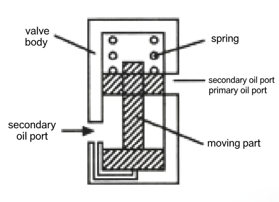
Figure 7-2 Normally closed pressure control valve (relief valve operation). The spring holds the spool closed until system pressure exceeds the spring setting, then the spool shifts and opens a path to tank.

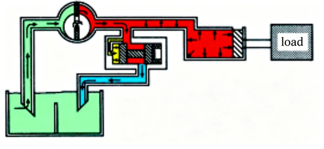
Figure 7-3 A simple hydraulic circuit with pressure control (relief valve). When the cylinder reaches end of stroke, the relief valve opens and routes pump flow back to tank, limiting maximum system pressure.
Once a hydraulic cylinder is fully extended, it must be retracted so that work can be done again. For this reason, cylinders that need to move in two directions normally use hydraulic cylinders with two ports — double-acting cylinders. The flow direction must be reversed at the same time.
A double-acting hydraulic cylinder has one port at each end of the barrel, allowing oil to enter and exit, so the piston can move in both directions (double-acting). To distinguish the two ports of a double-acting cylinder, we label one port "A" and the other "B".
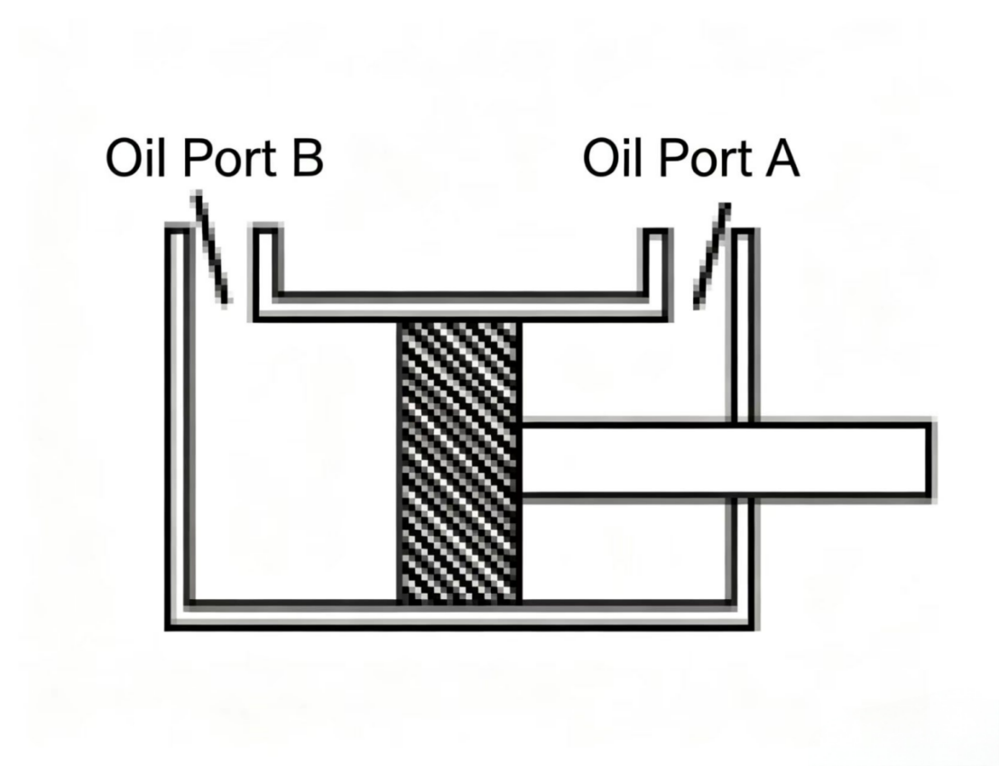
The internal moving parts of a directional control valve have the function of connecting or blocking the internal passages of the valve body, thereby controlling the direction of oil flow.
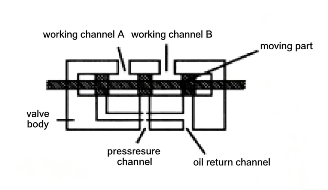
A typical directional control valve has four internal passages in the valve body and a sliding spool that can connect or block these passages.
When the spool is at one end position, the pressure passage connects to work passage A, and the return passage connects to work passage B. When the spool switches to the other end position, the pressure passage connects to work passage A, and the return passage connects to work passage B. Switching the direction of the spool switches the oil flow direction into the hydraulic cylinder.
When the cylinder rod fully extends and retracts as required, the work is done. When the spool switches to another end position, oil flows into the other side of the cylinder — and the cylinder rod retracts.
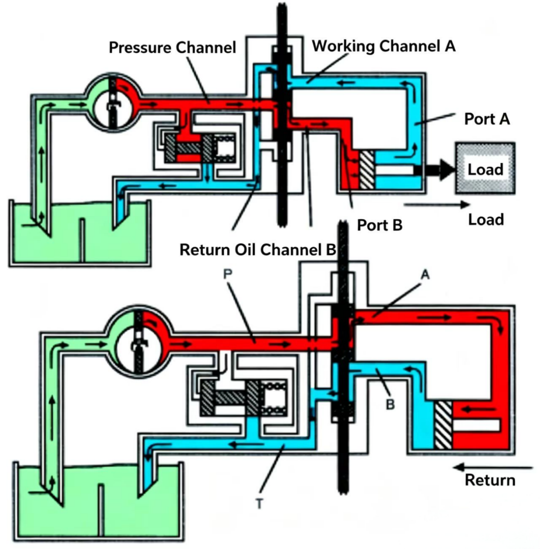
Figure 7-4 Directional control valve in a double-acting cylinder circuit. Shifting the spool reverses the oil flow direction, which reverses the cylinder motion.
In many applications, the working speed of the actuator must be controlled and sometimes very precisely controlled. As explained before, the speed of actuators (cylinders, hydraulic motors) is directly related to the rate of oil injection — the actuator speed is determined by the input flow rate.
Because the pump displacement can be fixed, it is possible to select the pump flow rate based on the required actuator speed. This is only viable in systems with a single actuator.
Usually in a hydraulic system the actuators are more than one. If the system requires each hydraulic cylinder to operate independently, the pump flow rate should be selected based on the largest hydraulic cylinder requiring the fastest speed. This means smaller actuators will move faster, which may not be desirable. To reduce the flow entering these or any other actuator, a flow control valve must be used.
When using a flow control valve, it is always possible to reduce the flow from the pump to the actuator.
A typical flow control valve consists of a valve body and a moving part. In our example, the moving part is a tapered-end adjusting needle. Because the needle does not actually move during operation (it is pre-set to a position), it is more appropriate to call the flow control valve moving parts "adjustable" rather than "moving".
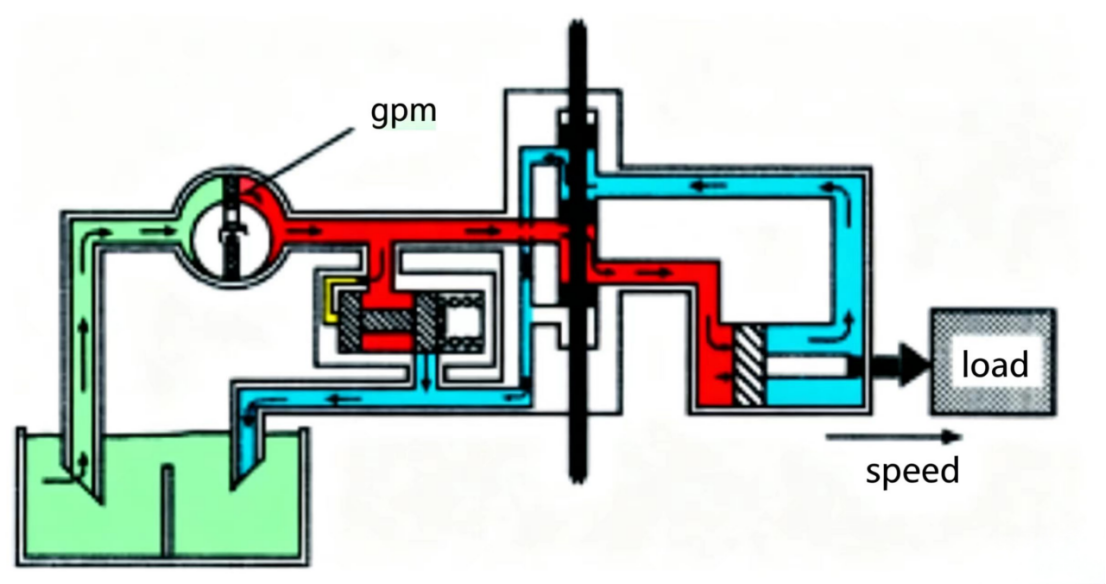
In a hydraulic system, the flow control valve always works with the pressure control (relief) valve. The flow control valve is a resistance. It causes the hydraulic pump to produce higher pressure. This pressure can cause part of the flow from the pump to open the relief valve, thereby reducing flow through the flow control valve and reaching the actuator.
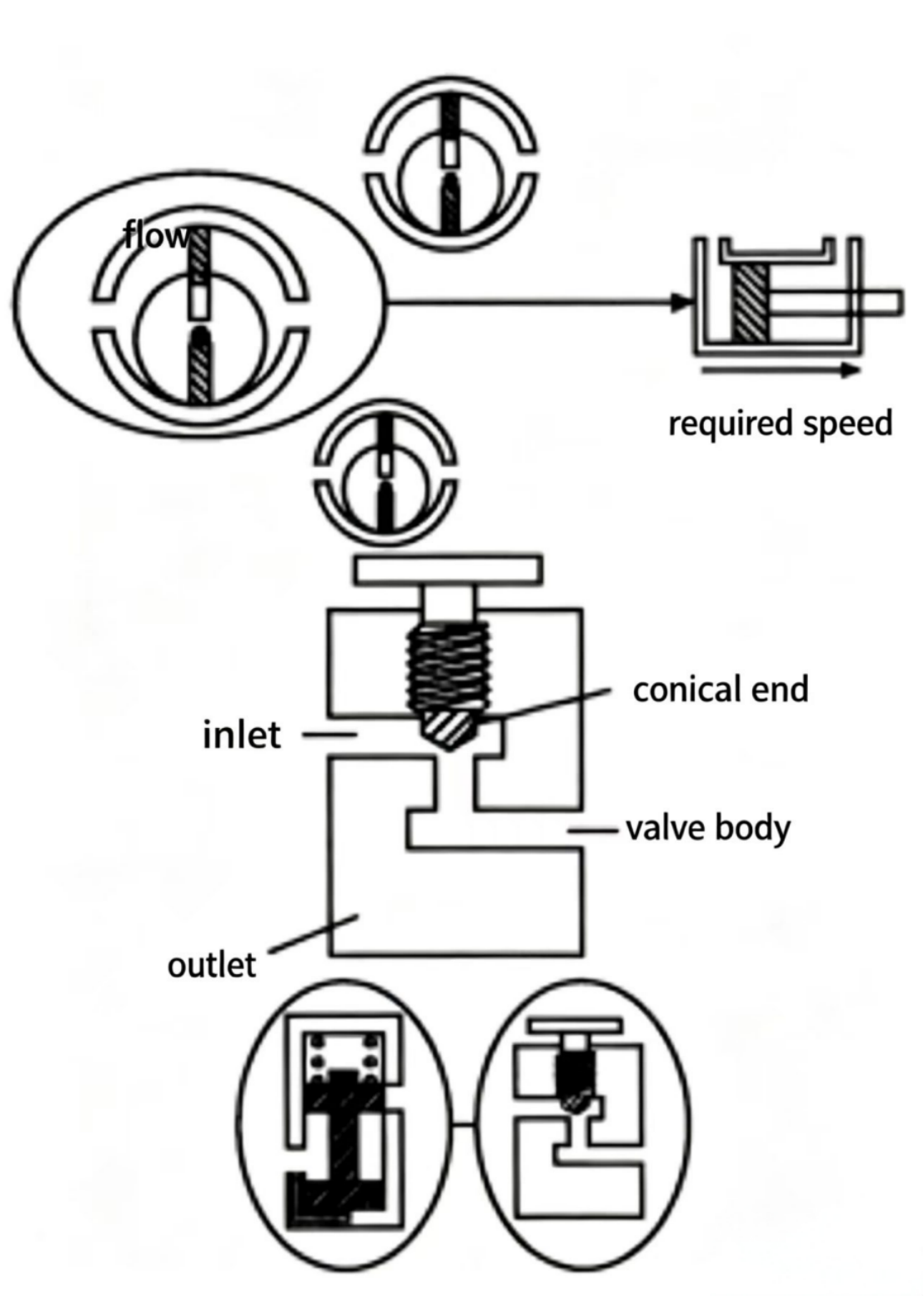
Figure 7-5 Flow control circuit. The needle valve throttles flow to the cylinder. Excess pump flow goes over the relief valve to tank. The needle valve opening determines cylinder speed.
All the components introduced above can make up a simple hydraulic system. Because the hydraulic energy in this system is controllable, this system can do useful work.
Hydraulic systems are widely used in many fields, from aerospace, aircraft, and military equipment to industrial, walking machinery, and steel equipment. The working principles of hydraulic systems in all these applications are the same as described above. The only difference between various "types" of hydraulic systems lies in the components used.
In the following chapters, we will discuss various types of components in detail — they are used in industrial hydraulic systems. To explain how to use these components, we will also design some basic hydraulic circuits.

In previous discussions of hydraulic components and basic systems, everything was explained graphically — using cross-sectional views to visually show component internal actions. This method is helpful for explaining problems, but is impractical from a day-to-day working perspective.
Like other technical fields, hydraulics also uses graphic symbols to represent components and systems. The various hydraulic components and simple systems discussed previously can all be represented using ANSI Y32.10 or ISO 1219 standard hydraulic and pneumatic graphic symbols.
In addition to the components already discussed, the components that make up a hydraulic system also include electric motors, hydraulic filters, etc. Hydraulic systems are usually driven by electric motors. Also, to maintain a reasonable level of cleanliness, hydraulic systems should use hydraulic filters to protect the oil from contamination.

Figure 7-7 Standard hydraulic graphic symbols (ANSI Y32.10 / ISO 1219). These symbols are used on all hydraulic circuit schematic diagrams instead of cross-sectional drawings.

Figure 7-8 A complete simple hydraulic circuit shown with standard graphic symbols. This is how hydraulic circuits are drawn in engineering practice.

Welcome to HOVOO, a Chinese seal factory. Production of PU, Rubber and PTFE seals. The seals include O-ring, piston seal, rod seal, Gray ring and gas seal.


 EN
EN
 AR
AR CS
CS DA
DA NL
NL FI
FI FR
FR DE
DE EL
EL IT
IT JA
JA KO
KO NO
NO PL
PL PT
PT RO
RO RU
RU ES
ES SV
SV TL
TL IW
IW ID
ID LV
LV SR
SR SK
SK VI
VI HU
HU MT
MT TH
TH TR
TR FA
FA MS
MS GA
GA CY
CY IS
IS KA
KA UR
UR LA
LA TA
TA MY
MY