33-99No. Mufu E Rd. Gulou District, Nanjing, China [email protected] | [email protected]
33-99No. Mufu E Rd. Gulou District, Nanjing, China [email protected] | [email protected]

A hydraulic cylinder converts hydraulic energy into straight-line or linear mechanical motion. Connected to a movable load, it does work.
As introduced in earlier chapters, a hydraulic cylinder mainly consists of a barrel, two closed end caps, a piston, a piston rod, and inlet and outlet ports. Each end has one port — one for oil in, the other for oil out.
图6-1 标准双作用液压缸。油从左侧端口进入,使连杆伸长;通过右侧接口的机油会收回它。
Throughout the cylinder stroke, hydraulic energy acts on the moving piston. The pressure produced by that hydraulic energy will not exceed the resistance produced by the load. For a cylinder of known dimensions, we need to know what working pressure produces a specific output force. This can be determined (ignoring friction) with the formula:
Pressure = Force / Area
When using this formula, either the area and pressure are given to find the output force, or the area and output force are known to find the pressure. In practice, we usually know the cylinder bore diameter and need to calculate the piston area — but calculating a circle area is just as simple as calculating the area of a square.
The area of a circle equals approximately 78.54% of the area of a square whose side equals the circle's diameter. More precisely:
Circle area = Diameter^2 x 0.7854
Another commonly used formula:
Circle area = pi x D^2 / 4

Figure 6-2 Circle area = D² × 0.7854. This simple formula is used constantly in hydraulic cylinder calculations.
The distance over which hydraulic energy acts determines how much work is done — this distance is the cylinder stroke. As noted earlier, using hydraulic pressure to amplify a force seems to cost nothing. In some specific situations — when the system is static — a small force can produce a very large force with no apparent sacrifice. But if this amplified force also causes movement, something is sacrificed: distance.
Every hydraulic cylinder has a volume (displacement) equal to its stroke (in) multiplied by its piston area (in²), giving a volume in in³ (cm³).
Cylinder volume = Piston area x Stroke
(in^3) = (in^2) x (in) or (cm^3) = (cm^2) x (cm)
Example: The top piston must move 2 in (5.08 cm) to make the lower cylinder piston move 1 in (2.54 cm). Both pistons do the same work. The top piston displaces 20 in³ (327.8 cm³) of fluid — and the lower cylinder piston is displaced by that same 20 in³ (327.8 cm³) of fluid.
The speed of a hydraulic cylinder piston rod depends on how fast fluid fills the chamber behind the piston. Piston rod speed formulas:
Rod speed (in/min) = Flow rate (gpm) x 231 / Piston area (in^2)
Rod speed (m/s) = Flow rate (Lpm) x 0.1667 / Piston area (cm^2)

A hydraulic motor is an actuator that converts hydraulic energy into rotary mechanical energy. This rotary energy is applied to a load via the drive shaft.
All hydraulic motors essentially consist of a housing with inlet and outlet ports, and a rotating assembly connected to the drive shaft.
The example shown is a vane-type hydraulic motor. The rotating assembly consists of a rotor and vanes that can slide freely in and out of rotor slots. The rotating assembly is mounted eccentrically inside the housing; the drive shaft connects to the load. When pressure oil enters the inlet chamber, the hydraulic energy acts on the exposed vane face in the inlet chamber. Because the area of the upper vane exposed to pressure oil is larger, the force on the rotor is unbalanced — the rotor turns.
As the oil reaches the outlet chamber with decreasing volume, it is discharged.
Note: Before this type of motor can operate normally, the vanes must be extended and must have a reliable seal with the housing. Unlike a hydraulic pump, the vanes cannot be pushed out by centrifugal force — the method of extending motor vanes will be discussed in a later chapter.
Figure 6-6 Vane motor operation. Pressure oil acts on the vane faces. Because the upper vane area exposed to pressure is larger than the lower vane area, the net force rotates the rotor.
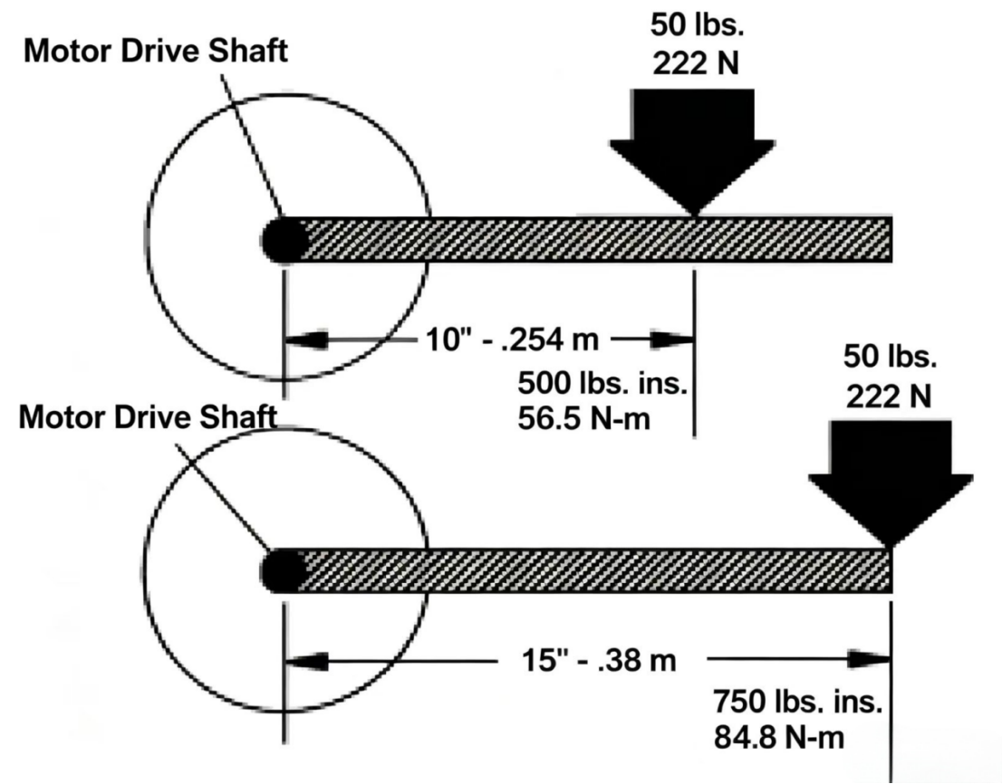
Torque is a rotational or twisting force. Torque is a force acting at a distance from a shaft centerline. The unit of torque is lb.in. (or Nm).
Torque tells us the position of the force relative to the hydraulic motor shaft centerline. The torque formula is:
Torque = Force x Distance from shaft center
(lb.in.) = (lbs) x (in.) or (Nm) = (N) x (m)
Example from the figure: A 50 lbs (222 N) force acts on a crank connected to the motor shaft. The distance between the shaft center and the force is 10 in. (0.254 m). The resulting torque on the shaft is 500 in.lbs (56.5 Nm). If the same 50 lbs (222 N) acts along a 15 in. (0.38 m) crank arm, the torque on the shaft is 750 in.lbs (84.6 Nm). The farther from the shaft center the force acts, the greater the torque. Note that torque does not involve any movement.
A load connected to the motor drive shaft produces torque as described above. For the hydraulic motor, this is resistance — it must be overcome by hydraulic pressure acting on the motor's rotating assembly.
Torque (in.lbs) = psi x Motor displacement (in^3) / (2 x pi)
Torque (Nm) = bar x Motor displacement (cm^3) / (20 x pi)
Hydraulic motor shaft speed is determined by how fast fluid is injected. The formula is:
Motor speed (rpm) = Flow rate (gpm) x 231 / Motor displacement (in^3/rev)
Motor speed (rpm) = Flow rate (Lpm) x 1000 / Motor displacement (ml/rev)
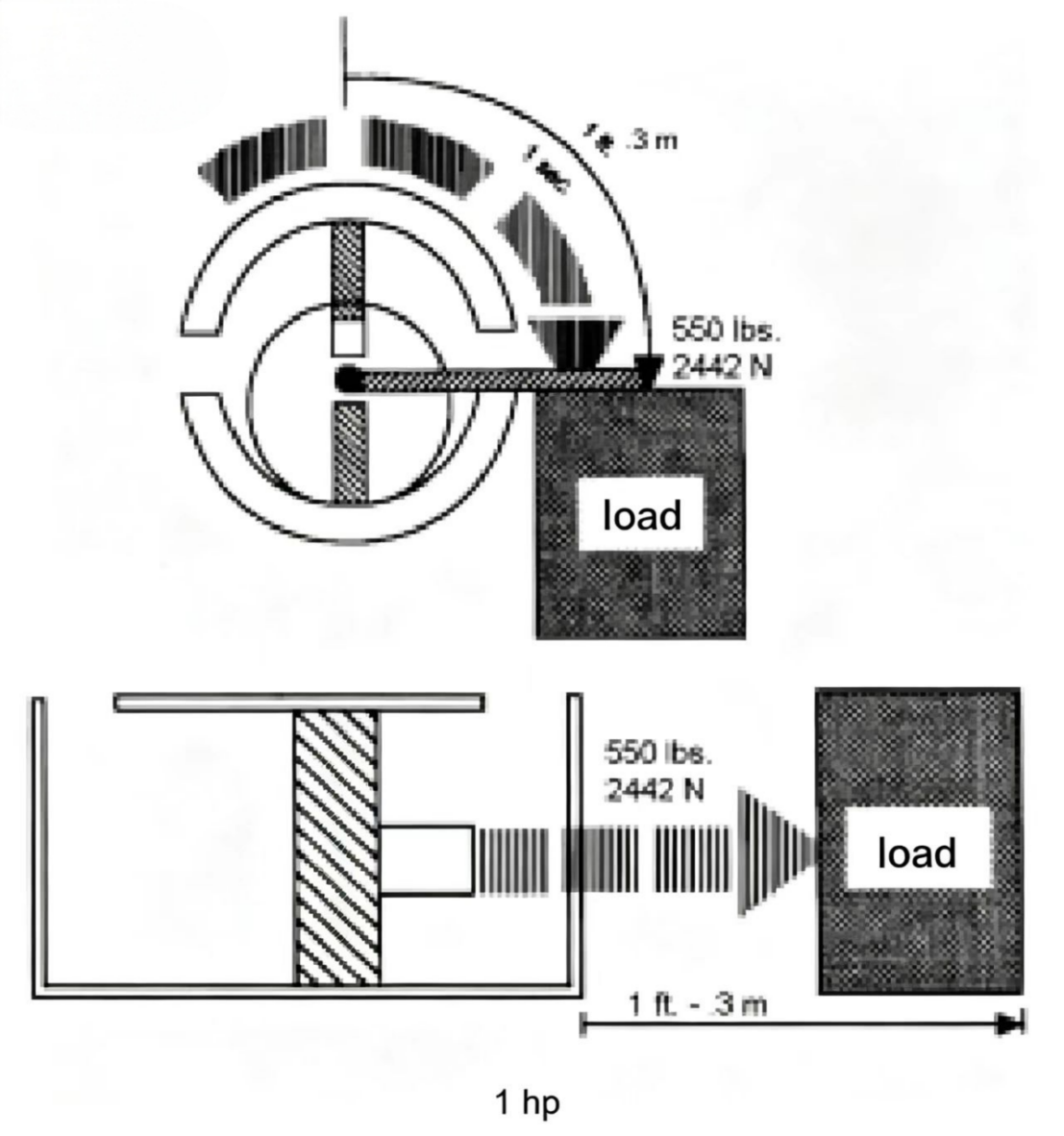
In earlier chapters we learned that power is the rate of doing work, i.e., hp = ft.lbs/time, or W = J/time.
We also know that horsepower (hp) or watt (W) is the unit of power. If a hydraulic cylinder or hydraulic motor drives a load with 550 lbs (2,442 N) of mechanical force and moves it 1 ft (0.30 m) in 1 second, it has used 1 hp (746 W) of power. If the same work (550 ft.lbs / 746 J) is done in half a second, the working speed doubles and the power is 2 hp (1,490 W).
The mechanical power transmitted by a cylinder or motor to a load equals the hydraulic power required of the cylinder or motor. For a hydraulic system doing work at a rate of 550 ft.lbs per second (746 J), its hydraulic power is 1 hp (746 W). However, in the mechanical power formula "ft (m)" and "lbs (N)" are replaced by hydraulic terms "psi (bar)" and "gpm (Lpm)". A conversion factor is used in hydraulic power calculations to express the relationship between gpm, psi, ft, and lbs (or Lpm, bar, m, N).
To calculate the power of a hydraulic cylinder or the entire hydraulic system:
hp = gpm x psi x 0.000583
W = hp x 746
W = (5/3) x Lpm x bar
To calculate hydraulic motor output power:
hp = rpm x Torque (in.lbs) / 63,025
kW = rpm x Torque (Nm) / 9,543
So far we have discussed hydraulic motors with rotary output and hydraulic cylinders with linear output. Now we will discuss another type of actuator that produces limited-angle rotation. This type is called an oscillating cylinder or oscillating motor. Its structure is compact, simple, and efficient — it produces high torque and requires only a small installation space, with easy installation.
Oscillating actuators are used for machine tool indexing, bending operations, lifting or rotating heavy objects, flipping, positioning, machining fixtures, nautical controls, valve operation, etc.
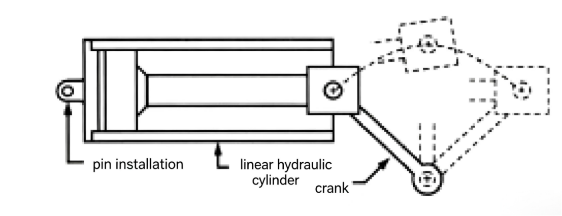
There are many types of oscillating cylinders. The simplest is a linear hydraulic cylinder-driven oscillating mechanism where the cylinder barrel end is mounted with a pin, and the piston rod connects to a crank that drives a shaft to rotate. This oscillating cylinder can be controlled by a 4-way directional valve, with limit switches at each end of stroke.
Like all mechanical devices, this linear cylinder-based oscillating actuator has some basic characteristics, including that it can be assembled from standard off-the-shelf parts, giving designers great flexibility and keeping costs low with easily obtainable spare parts.
However, this type of oscillating actuator also has undesirable features: the piston rod is unprotected and directly contacts the surrounding environment, especially as the crank mechanism is usually not sealed, creating safety hazards. Also, the drive shaft typically bears large lateral loads, causing early failure, excessive wear, and binding.
For this specific type of oscillating actuator, the hydraulic cylinder must be free to swing, so it must use flexible hose connections, and throughout the cylinder stroke, the output torque is not constant.
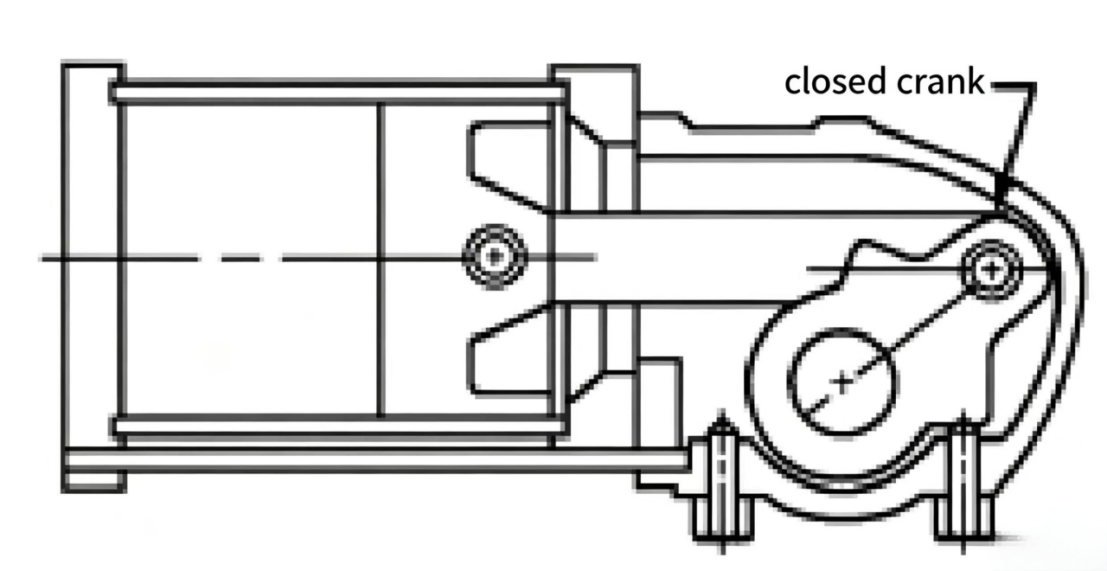
The enclosed oscillating cylinder is very similar to the linear cylinder-based oscillating mechanism above. The enclosed cylinder has a protective cover that encloses the piston rod and crank. The drive shaft typically has additional bearing support to prevent severe lateral loads. This type can be fitted with solenoid valves, limit switches, or stroke switches. Stroke range can usually be adjusted between about 85° to 100°.
Another type is the spring-return oscillating cylinder, which uses a hydraulic cylinder with a return spring to return the drive shaft to its original position. Spring-return oscillating cylinders can output torques up to 5,000 in.lbs (565 Nm).

The most common oscillating cylinder is the rack-and-pinion type. This type can maintain constant output torque in both directions throughout the full rotation. In this configuration, hydraulic pressure acts on the piston, pushing the rack connected to the piston, which drives the pinion gear to rotate the shaft. Standard rack-and-pinion cylinders have rotation strokes of 90°, 180°, 360°, or even larger. Rack-and-pinion cylinder output torques can reach 52,000,000 in.lbs (5,876,000 Nm).

There is also a vane oscillating motor available. This type can be single-vane or multi-vane. A single-vane motor can rotate 280°; a dual-vane motor can rotate 200°. Dual-vane output torque is twice that of single-vane. This type of oscillating motor can achieve output torques up to 500,000 in.lbs (Nm).

There is another type of oscillating motor that generates torque using a helical spline mechanism. Changes in spline length and pitch allow the rotation stroke to vary over a wide range. This type of oscillating motor has one helical spline shaft with an internally splined piston sleeve on the shaft — the piston sleeve rotation is constrained by guide rods. When the piston sleeve moves inside the cylinder, it drives the spline shaft to rotate. Standard rotation strokes are 90°, 180°, 270°, and 360°, with output torques up to 1,000,000 in.lbs (13,000 Nm).
Chain-and-sprocket oscillating motors use pistons, chains, and sprockets to drive the shaft. This actuator typically has one large piston (as drive device) to pull the chain, and a small piston to prevent oil from leaking through the return chain route. Output torques can reach about 23,000 in.lbs (2,599 Nm), and the drive shaft rotation can reach five full turns or 1,800°.
For selecting the most suitable oscillating cylinder for a specific application, matching torque, speed, and operating method are all involved. We will describe actual oscillating motor selection in another chapter, and further discuss how to determine single or double-acting, whether to use closed-loop positioning, whether cushioning is needed, etc. Operating frequency or cycle period will also be examined.
Actuator speed is a function of flow rate gpm (L/min)
The linear speed of a hydraulic cylinder piston rod depends on the speed at which the pump injects fluid into the cylinder piston chamber gpm (L/min). The rotational speed of a hydraulic motor drive shaft depends on the flow rate gpm (L/min) injected into the hydraulic motor.
Actuator output force is a function of pressure psi (bar)
The output force of a cylinder is expressed in psi (bar) — the output force on a motor drive shaft is determined by the pressure acting on the exposed area of the motor's rotating assembly. The power produced by an actuator is a function of actuator speed multiplied by actuator output force.
For cylinders, output force is expressed in psi, and piston rod speed in gpm. The constant 0.000583 describes the relationship between psi, gpm, and power. For motors, output force is expressed in torque, and motor operating speed in rpm. The constant 63,025 describes the relationship between rpm, torque, and power.

Welcome to HOVOO, a Chinese seal factory. Production of PU, Rubber and PTFE seals. The seals include O-ring, piston seal, rod seal, Gray ring and gas seal.


 EN
EN
 AR
AR CS
CS DA
DA NL
NL FI
FI FR
FR DE
DE EL
EL IT
IT JA
JA KO
KO NO
NO PL
PL PT
PT RO
RO RU
RU ES
ES SV
SV TL
TL IW
IW ID
ID LV
LV SR
SR SK
SK VI
VI HU
HU MT
MT TH
TH TR
TR FA
FA MS
MS GA
GA CY
CY IS
IS KA
KA UR
UR LA
LA TA
TA MY
MY