33-99No. Mufu E Rd. Gulou District, Nanjing, China [email protected] | [email protected]
33-99No. Mufu E Rd. Gulou District, Nanjing, China [email protected] | [email protected]

In industrial hydraulic systems, the pump is usually mounted on top of the reservoir that holds the system fluid. The suction line (also called the inlet line) connects the pump inlet to the oil in the reservoir.
The flow of fluid from the reservoir to the pump can be thought of as a separate hydraulic system. In this sub-system, the below-atmospheric pressure created by the pump provides the resistance to flow, and the energy that moves the fluid comes from atmospheric pressure. The atmosphere, acting on the oil surface in the reservoir, works like an accumulator.

Figure 5-1 Standard pump installation — pump on top, suction line below oil level. Atmospheric pressure acting on the oil surface is what pushes oil up into the pump.
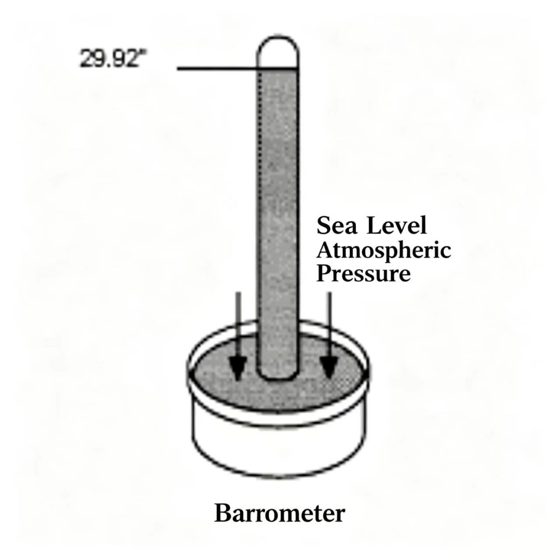
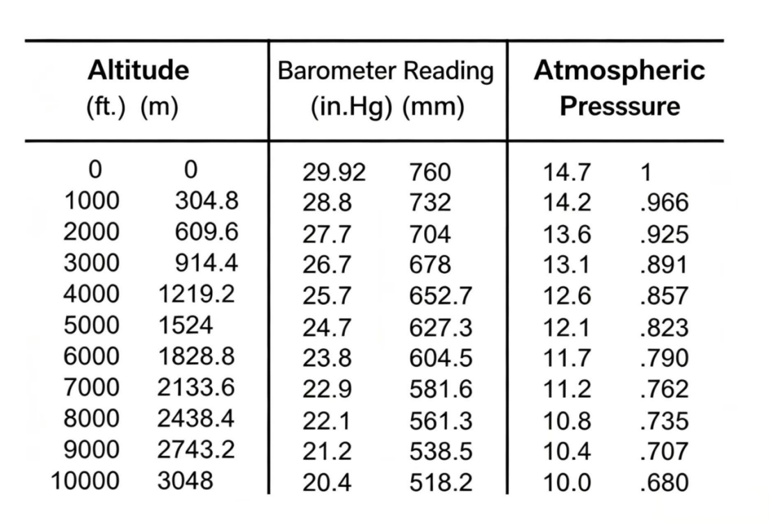
We generally think of air as having no weight, but the atmosphere of air surrounding the Earth does in fact have pressure. Torricelli, the inventor of the barometer, showed that atmospheric pressure can be measured using a mercury column. By inverting a mercury-filled tube into a mercury trough, he found that at sea level the mercury column that atmospheric pressure can support stands at 29.92 in (760 mm). So at standard conditions, sea-level atmospheric pressure equals (or is equivalent to) a 29.92 in (760 mm) mercury column. Of course, any location above sea level will have a lower atmospheric pressure.
Hydraulic pressure is usually expressed in psi or bar, but atmospheric pressure is usually measured in in.Hg (inches of mercury) or mmHg. At 68°F (20°C) and 36% relative humidity, sea-level atmospheric pressure = 29.92 in.Hg or 760 mmHg, equivalent to 14.7 psia or 1.01 bar. Importantly, bar is not used to define atmospheric pressure; instead, standard atmospheric pressure is 101,000 N/m².
When converting between in.Hg and psi, note that 1 psia = 2.04 in.Hg, and 1 bar ≈ 752 mmHg. So approximately: 1 psia ≈ 2 in.Hg, or 1 bar ≈ 750 mmHg.
Both absolute pressure and gauge pressure can be used to measure pressure in a hydraulic system.
Absolute pressure is measured from the zero-pressure point — the point of complete absence of pressure. The unit can be psi (bar) or in.Hg (mmHg). Absolute pressure is designated by adding an "a" suffix: psia (absolute psi), bara.
Gauge pressure is measured from the atmospheric pressure reference point. The unit is psi (bar). Absolute pressure equals gauge pressure plus standard atmospheric pressure. Example: if a system reads 100 psig (6.9 bar gauge) and standard atmospheric pressure is 14.7 psia (1 bar), the absolute pressure is 114.7 psia (7.9 bar absolute). To distinguish the two, gauge pressure is written as psig, and absolute as psia.

When the pump is not running, the inlet side of the system is in equilibrium — the pressure difference between the pump and the atmosphere is zero, meaning there is no flow. For the pump to supply oil to its rotating assembly, the running pump creates a pressure below atmospheric — the system becomes unbalanced — and flow begins.
The pressure that atmospheric pressure exerts on the fluid serves two purposes:
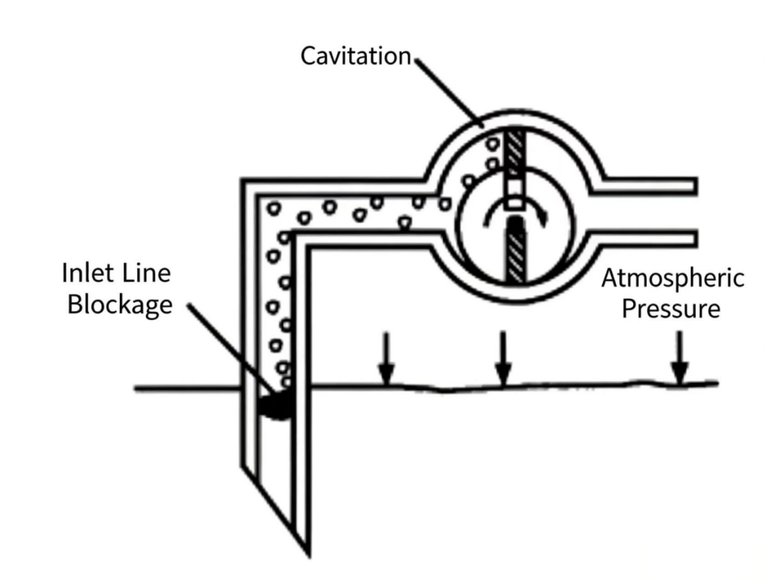
Most atmospheric pressure is used to accelerate fluid into the pump, but the first job must be done first: supplying fluid to the pump inlet. If too much atmospheric pressure is consumed at this stage, there will not be enough pressure left to accelerate fluid into the rotating assembly. This causes the pump to starve, and what is known as cavitation occurs.
Cavitation is the formation and collapse of vapor cavities in a liquid. It harms the pump in two ways:
On the pump inlet side, vapor cavities form throughout the fluid. This reduces lubrication effectiveness and accelerates wear. When these cavities reach the high-pressure zone at the pump outlet, the cavity walls are compressed and collapse violently, releasing enormous energy that "chips away" at metal surfaces — just like a sculptor using a hammer and chisel on stone. If cavitation is allowed to continue, pump life is shortened, and cavitation debris can travel to other parts of the system and damage other components.
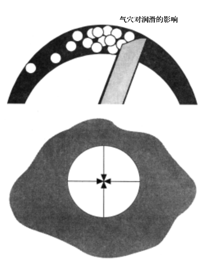
Figure 5-5 Cavitation damage on the pump housing bore. The microscopic pitting pattern is caused by repeated implosion of vapor cavities at the metal surface.
The most obvious sign of cavitation is noise — when cavities collapse, they generate high-amplitude vibration that spreads through the entire system, and the hydraulic pump produces a high-pitched, piercing sound. When cavitation occurs, because the pump chambers are not completely filled with fluid, flow decreases and system pressure becomes unstable.
Cavitation forms in a liquid because the liquid boils — but this boiling is not caused by heat. It is caused by the liquid reaching a sufficiently low absolute pressure.
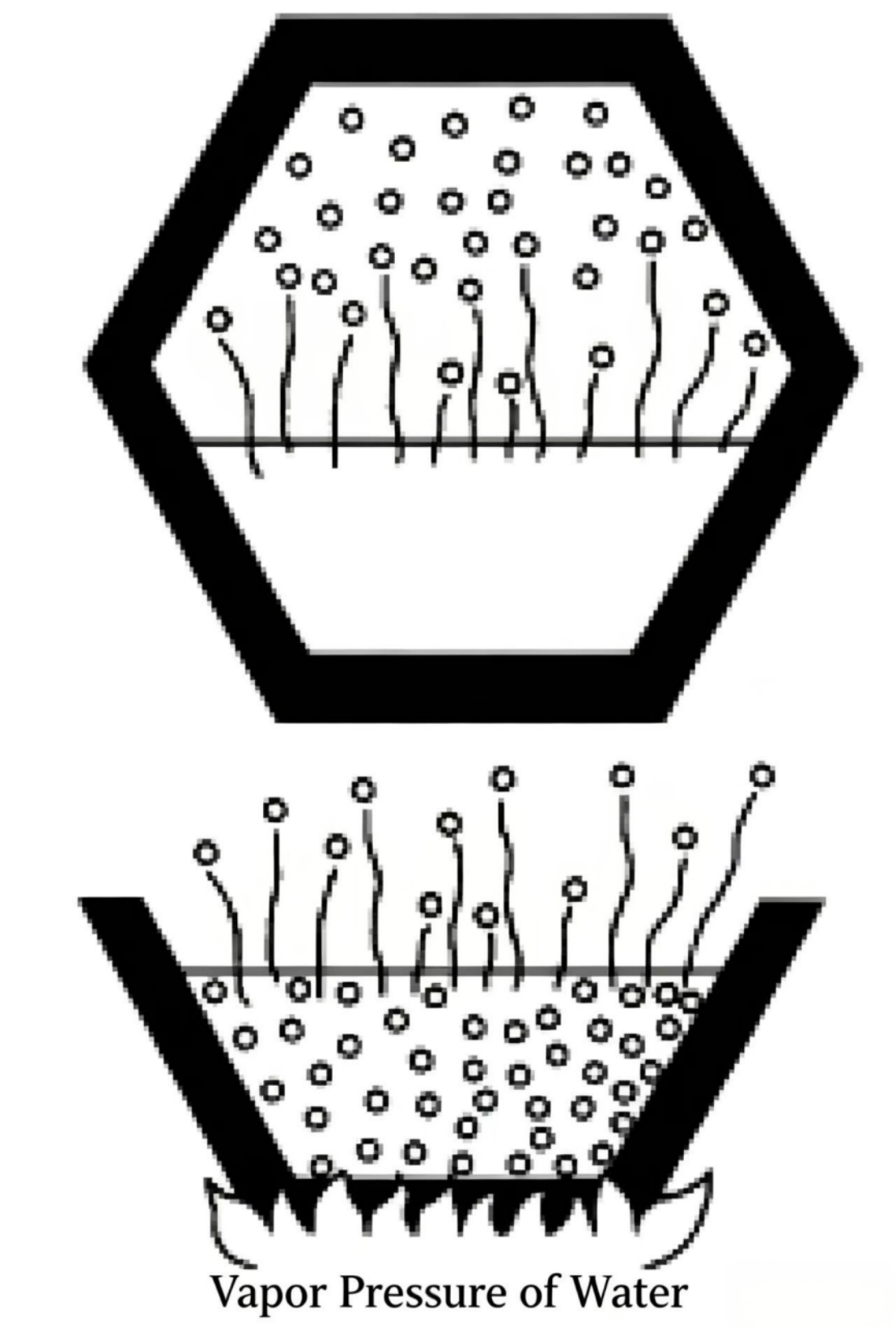
All molecules in a liquid are in constant motion, but not all at the same speed. Faster-moving molecules near the surface try to escape into the space above, despite the attraction of surrounding molecules. The force that fast-moving molecules need to overcome to escape into the atmosphere is the vapor pressure of the liquid.
If the liquid container is sealed, fast-moving molecules enter the space above the liquid. When that space reaches vapor saturation, molecules collide and return to the liquid. Molecules leaving is called evaporation; molecules returning is liquefaction. When evaporation and liquefaction rates are equal, equilibrium is reached and the pressure generated by the vapor is the vapor pressure of that liquid. Vapor pressure is typically expressed in absolute pressure units, in.Hg.
Vapor pressure is affected by temperature. As temperature rises, liquid molecules get more energy and move faster. Vapor pressure rises. When vapor pressure equals atmospheric pressure, liquid molecules can freely enter the atmosphere — this is called boiling. Water at sea level boils at 212°F (100°C), because at this temperature water's vapor pressure equals atmospheric pressure.
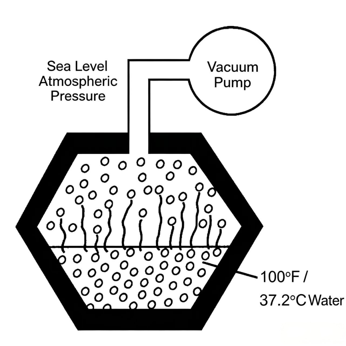
A liquid can also be made to boil by lowering the pressure acting on it. When the reduced pressure equals the liquid's vapor pressure, liquid molecules can freely enter the space above the liquid. Water at 100°F (37.2°C) has a vapor pressure of 2 in.Hg (0.068 bar). If a container of water at 100°F is connected to a vacuum pump and the internal absolute pressure drops to 2 in.Hg (0.068 bar), the water boils. Pumps handling a liquid generally experience this type of boiling.

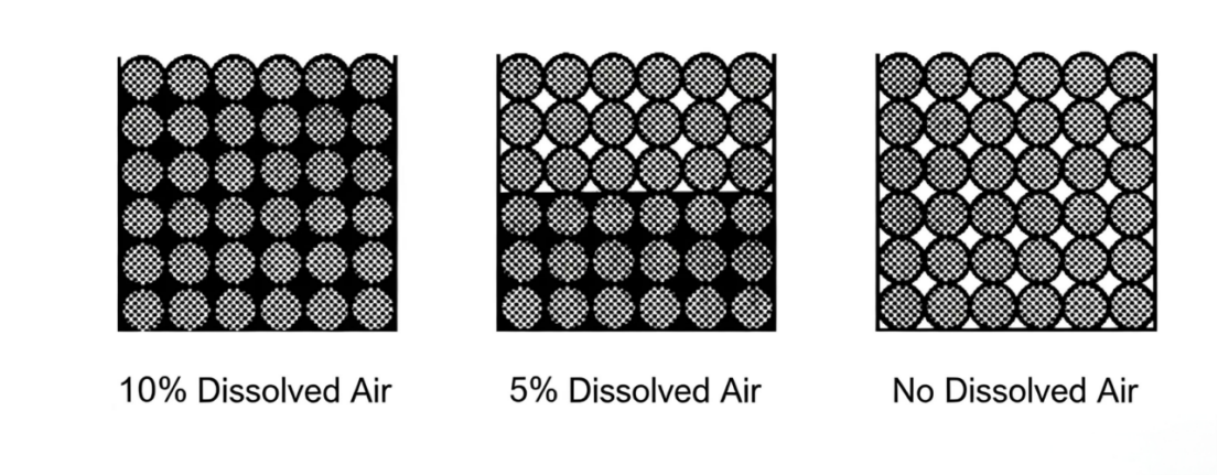
Hydraulic oil at sea level contains about 10% dissolved air. This air exists dissolved in the liquid — it is invisible and does not noticeably increase the liquid volume. The ability of hydraulic oil or any liquid to dissolve air decreases as the pressure acting on the liquid decreases. For example, if a cup of hydraulic oil under atmospheric pressure is placed in a vacuum, the dissolved air converts to bubbles and escapes from the solution. During cavitation, dissolved air escapes from the oil and causes damage to the hydraulic pump.
Entrained air is air in the liquid in an undissolved state — as bubbles. If a pump occasionally draws in oil containing entrained air, the air bubbles have effects similar to cavitation on the pump. However, because it is not related to the liquid's vapor pressure, we call it pseudo-cavitation.
If there are leaks in the suction line or the pump shaft seal fails, entrained air is almost always present in the system. Because the pressure at the pump inlet side is often below atmospheric, any opening there will cause air to be drawn into the oil and into the pump. Any entrained air bubbles that cannot escape in the reservoir will also enter the pump.
Cavitation is highly damaging to both the pump and the system. For this reason, pump manufacturers specify inlet-side limits for their products. Positive-displacement industrial hydraulic pump manufacturers generally specify that the pressure at the pump inlet must be below atmospheric pressure so that fluid can be injected into the pump's rotating assembly. However, this pressure specification is usually not given in absolute pressure units — it is given in terms of vacuum.
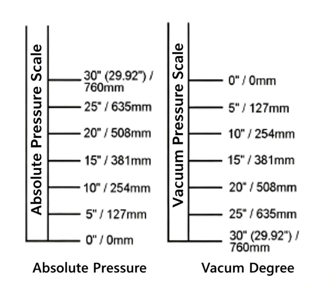
A vacuum is any pressure below atmospheric. Vacuum is a confusing concept because its starting point is the same as gauge pressure (atmospheric), but the values are counted downward in in.Hg (mmHg) units.
0 in (0 mm) vacuum = atmospheric pressure or zero gauge pressure. 29.92 in.Hg (760 mmHg) vacuum = complete vacuum or zero absolute pressure.
As shown in the diagram, a mercury trough connected via a glass tube to a container at atmospheric pressure: since the pressure inside the container equals the atmospheric pressure acting on the trough, the mercury does not rise in the glass tube. The zero mercury column height indicates the container is not in a vacuum.
If the container is evacuated until internal pressure drops 10 in.Hg (254 mmHg), the atmospheric pressure acting on the trough surface can then support 10 in. (254 mm) of mercury — the measured vacuum is 10 in.Hg (254 mmHg). If the container is evacuated to complete vacuum (zero absolute pressure), atmospheric pressure can support 29.92 in. (760 mm) of mercury — measured vacuum is 29.92 in.Hg (760 mm).
0 in. (0 mm) mercury vacuum = atmospheric pressure = zero gauge pressure. 29.92 in.Hg (760 mm) vacuum = complete vacuum = zero absolute pressure.
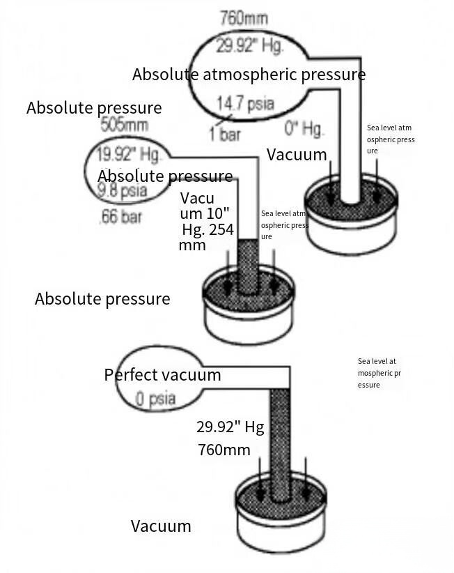
Figure 5-9 Vacuum measurement with a mercury manometer. The three states from top to bottom: atmospheric (0 vacuum), partial vacuum (10 in.Hg), and complete vacuum (29.92 in.Hg = 0 psia).
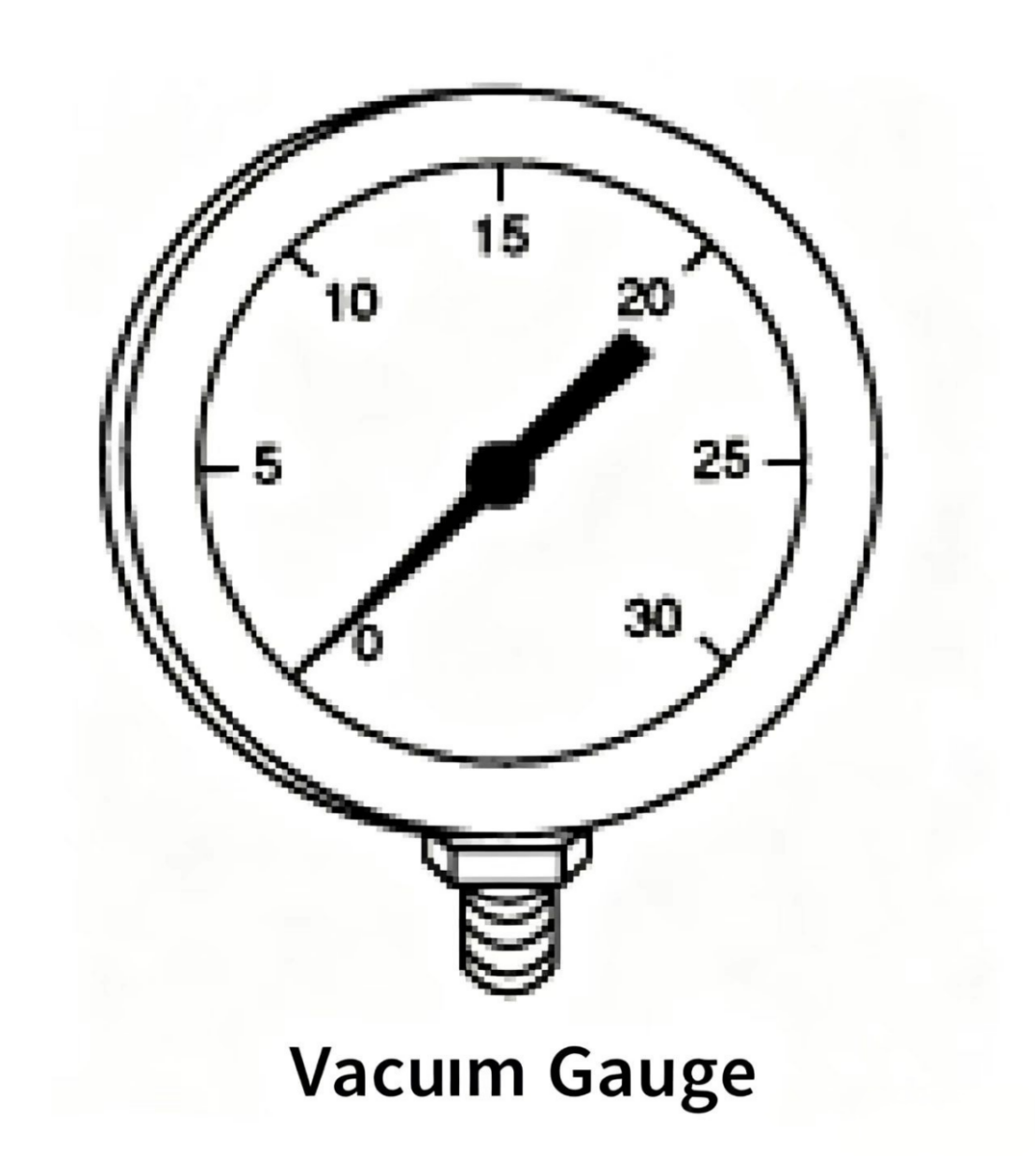
A vacuum gauge is calibrated from 0 to 30 in.Hg (0–760 mmHg), with each division being 1 in.Hg. At sea level, to convert a vacuum gauge reading to absolute pressure, simply subtract the vacuum reading (in in.Hg) from 30 in.Hg (760 mmHg). For example, a 7 in.Hg (177 mmHg) vacuum reading equals an absolute pressure of 23 in.Hg (583 mmHg).
Pump manufacturers use vacuum units for inlet requirements because it is related to sea level — when the pump is used at altitudes above sea level, the lower atmospheric pressure at that altitude must be considered.
Example: If a manufacturer specifies the maximum inlet vacuum must not exceed 7 in.Hg (177 mmHg), this means the manufacturer wants at least 23 in.Hg (583 mmHg) of absolute pressure (or atmospheric pressure) at the pump inlet to accelerate fluid into the rotating assembly. If the absolute pressure at the pump inlet falls below 23 in.Hg (583 mmHg), the pump may be damaged, though this depends on the design factor the manufacturer allows for the vacuum rating. All published pump inlet specifications assume rated speed and petroleum oil. If the pump runs at a different speed or uses a different fluid, the specifications must be adjusted.
The pump's maximum allowable vacuum depends on which fluid is being pumped. Inlet-side technical requirements are calculated based on the specific gravity and vapor pressure of petroleum oil. If fire-resistant hydraulic fluids are used, changes in specific gravity and vapor pressure will affect the maximum allowable inlet vacuum.
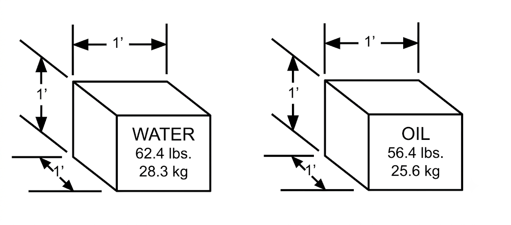
Specific gravity is the ratio of the weight of one liquid to the weight of another liquid. More precisely, it is the ratio of the weight of a fixed volume of liquid to the weight of the same volume of water. At 60°F (15.6°C), 1 ft³ of water weighs 62.4 lbs (28.3 kg). Dividing the oil weight by the water weight, we find that oil weighs 90% as much as water, or the weight ratio is 1 (water) to 0.90 (petroleum oil) — the specific gravity (SG) of petroleum oil is therefore 0.90.
Pump inlet-side requirements are calculated for petroleum oil with SG 0.87–0.90. For phosphate ester fire-resistant fluid, SG increases by 30%, to about 1.15. Water-based hydraulic fluid SG ranges from 0.93 (HFB emulsion) to 1.08 (water-glycol). To accelerate these heavier fluids into the pump, higher pressure is needed at the pump inlet. Therefore, the maximum allowable vacuum should be slightly reduced.
Petroleum oil and phosphate ester fire-resistant fluids at normal hydraulic operating temperatures have very low vapor pressures, but water-based hydraulic fluids are different. Water-based fluids contain a high proportion of water. The vapor pressure of both HFB emulsion and water-glycol can reach several inches of mercury, while petroleum oil and synthetic fluids have vapor pressures of only a fraction of an inch of mercury. Therefore, water-based fluids are more prone to evaporation and cavitation.
To prevent water-based fluids from cavitating, pump manufacturers require sufficient pressure at the pump inlet to accelerate the working fluid into the pump. This requirement can be met by reducing the maximum allowable vacuum.

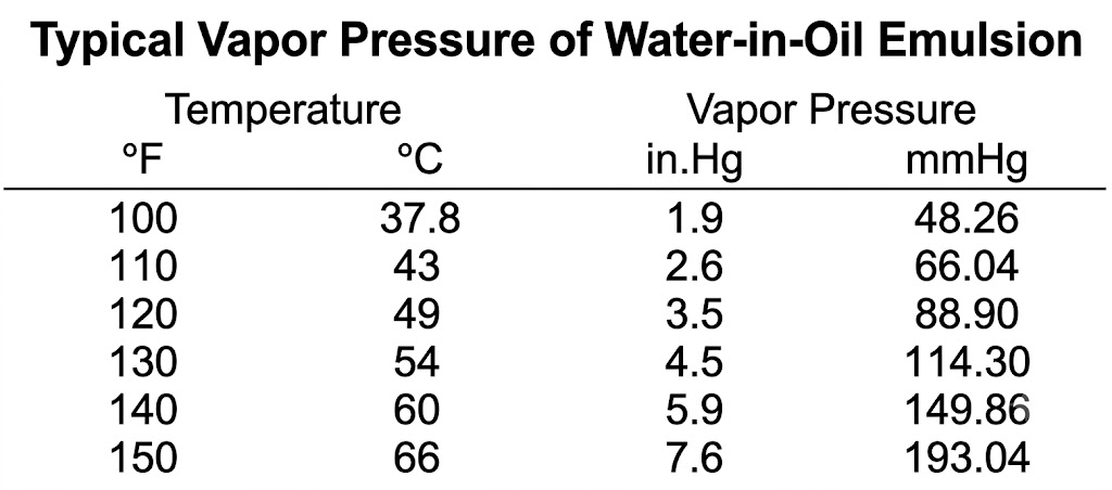
Figure 5-13 Vapor pressure comparison. Water-based fluids have much higher vapor pressure than mineral oil at the same temperature, making them more prone to cavitation if inlet vacuum is too high.
Maintenance personnel are most likely to discover a pump developing cavitation or drawing in air early, because their familiarity with the machine enables them to notice the first signs of a fault.
The most obvious sign of hydraulic pump cavitation or air ingestion is a high-pitched sound, but there are subtle differences: a cavitating pump produces a steady high-pitched sound — this sound may be caused by bubbles of similar size collapsing. When drawing in air, the pump sound varies greatly: when a small amount of air enters, the noise sounds like clicking or like a bearing failure; if large amounts of air enter, it produces a strange hammering or crackling sound.
A more reliable way to distinguish cavitation from air ingestion is to use a vacuum gauge to determine the absolute pressure at the pump inlet. Subtract the vacuum reading from atmospheric pressure; if the absolute pressure value is insufficient, cavitation may be occurring.
For new hydraulic systems: if the pump cavitates, it may be because the suction line is poorly designed, or the oil viscosity is too high. Using oil with the correct viscosity or increasing the suction line diameter to reduce line pressure drop will help improve cavitation. For a correctly designed existing system: if the pump cavitates, it may be due to the suction line being blocked by debris, paper, or small animals — or the inlet filter may be too dirty without a bypass, or the bypass is not opening enough.
For hydraulic pumps, "priming" means filling the pumping mechanism with fluid. An unprimed pump contains air or "air locks." Before pumping action begins, this air must be cleared from the suction line and pump cavity. If this step is skipped, the hydraulic pump started without priming may cause permanent damage within a few minutes from lack of lubrication.
A pump whose outlet is connected directly to the reservoir through a directional valve can generally easily exhaust residual gas into the reservoir at startup. If the pump must exhaust the internal air through the relief valve, this operation may not be possible — because a typical industrial hydraulic pump is a very poor air compressor.
To exhaust residual air from an unprimed pump, loosen the pipe fitting at the pump outlet, slowly rotate the pump until oil squirts out of the fitting, indicating the pump is primed, then tighten the fitting. Residual air can also be exhausted by unloading the relief valve.
Hydraulic pumps typically only need priming when starting a new system or when suction-side maintenance has been done on an existing system.
The following terms and formulas are used when working with pump inlet conditions:
The condition where the pump inlet is below the reservoir fluid level. With flooded suction, the fluid head (gravity) provides additional energy to push fluid into the pump.
The pressure at the bottom of a fluid column. When the pump inlet is below the fluid level, head pressure provides an additional energy source for the pump. Head pressure formulas:
Head pressure (in.Hg) = Height (in) x 0.036 x Specific Gravity / 0.491
Head pressure (mmHg) = Height (mm) x 0.0288 x Specific Gravity
The equivalent column height expressed in length units, below a given reference point. Lift pressure formula (in in.Hg):
Lift pressure (in.Hg) = Height (in) x 0.036 x Specific Gravity / 0.491
Lift pressure (mmHg) = Height (mm) x 0.0288 x Specific Gravity
The action a hydraulic pump performs to create a pressure difference between itself and the atmosphere.
The absolute pressure of the fluid at the pump inlet.

Welcome to HOVOO, a Chinese seal factory. Production of PU, Rubber and PTFE seals. The seals include O-ring, piston seal, rod seal, Gray ring and gas seal.


 EN
EN
 AR
AR CS
CS DA
DA NL
NL FI
FI FR
FR DE
DE EL
EL IT
IT JA
JA KO
KO NO
NO PL
PL PT
PT RO
RO RU
RU ES
ES SV
SV TL
TL IW
IW ID
ID LV
LV SR
SR SK
SK VI
VI HU
HU MT
MT TH
TH TR
TR FA
FA MS
MS GA
GA CY
CY IS
IS KA
KA UR
UR LA
LA TA
TA MY
MY