33-99No. Mufu E Rd. Gulou District, Nanjing, China [email protected] | [email protected]
33-99No. Mufu E Rd. Gulou District, Nanjing, China [email protected] | [email protected]

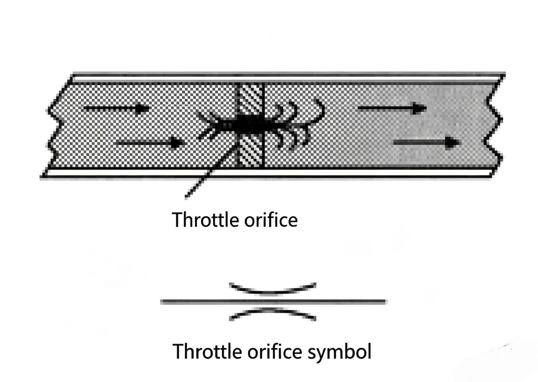
An orifice is a relatively small opening in a fluid flow path. The flow through an orifice is influenced by several factors, the three main ones being:
The orifice size controls the flow through it. A common everyday example is a garden hose nozzle — if the nozzle opening is small, the water comes out as a fine mist or spray. If the opening is larger, it becomes a jet stream. In both cases the hose nozzle orifice limits the water flow direction — the flow through the orifice is determined by the opening size.
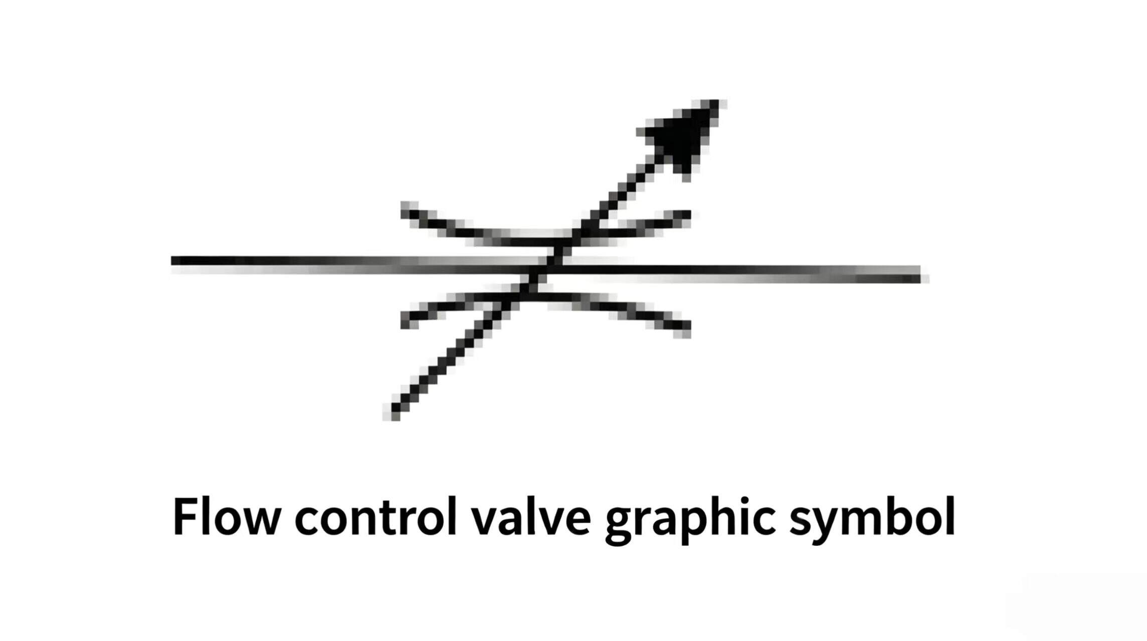
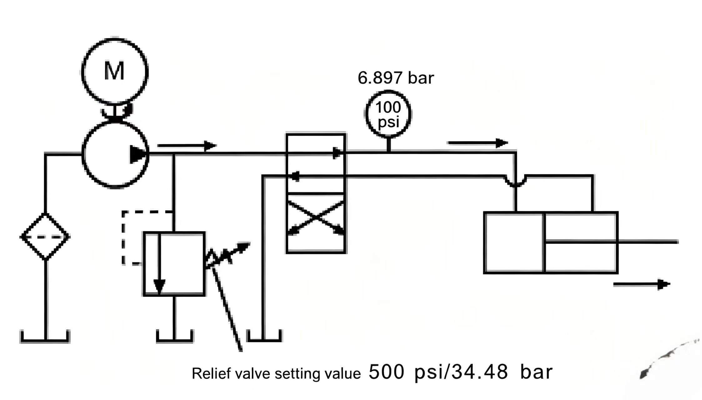
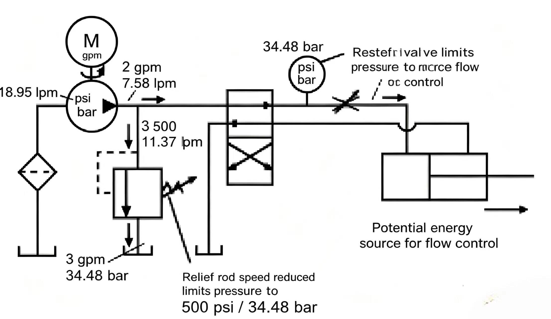
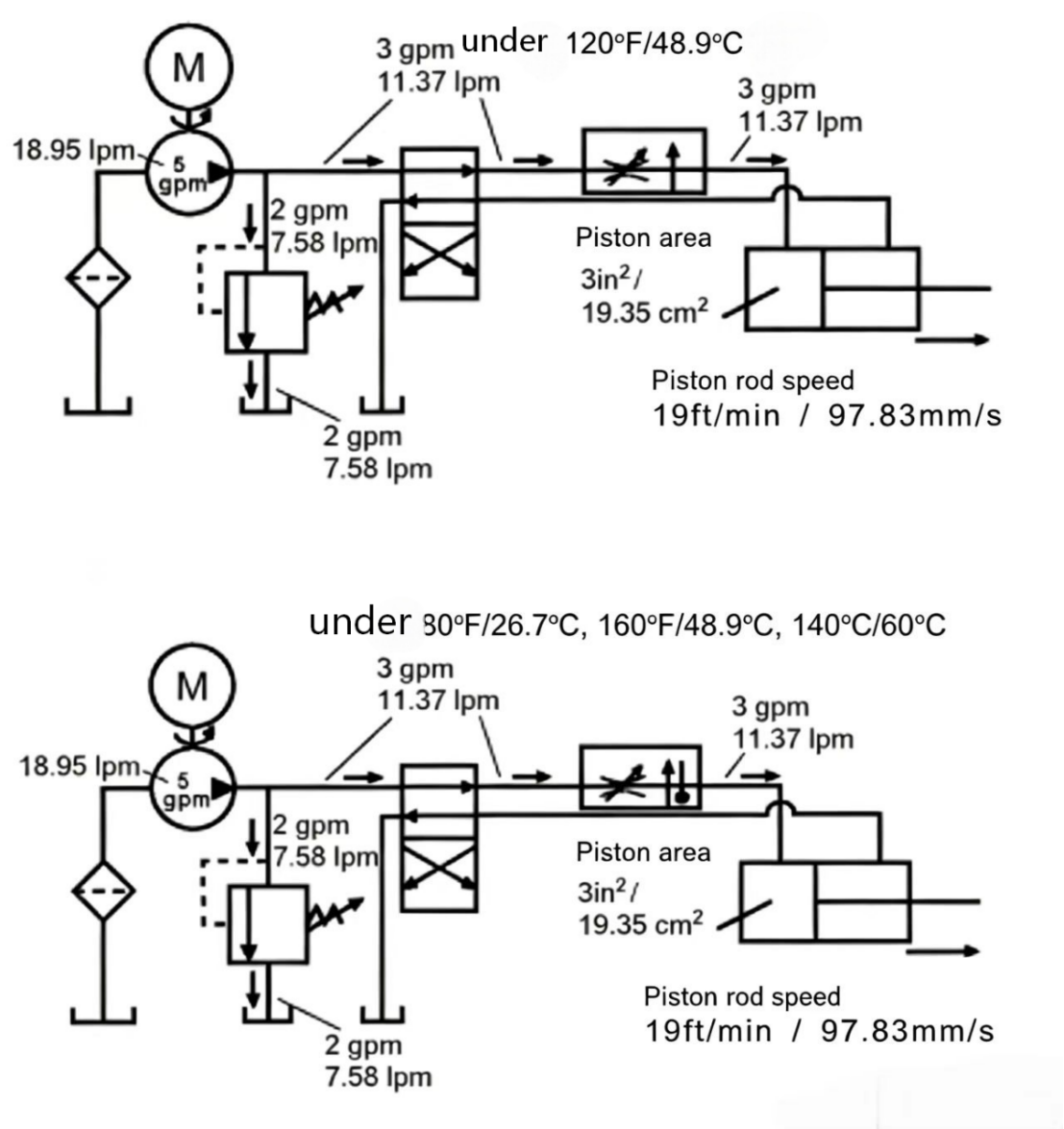
Figure 9-1 Flow control valve in a circuit. The valve throttles flow to the cylinder. Excess pump flow goes over the relief valve. The restricted flow becomes potential energy (velocity) at the orifice.
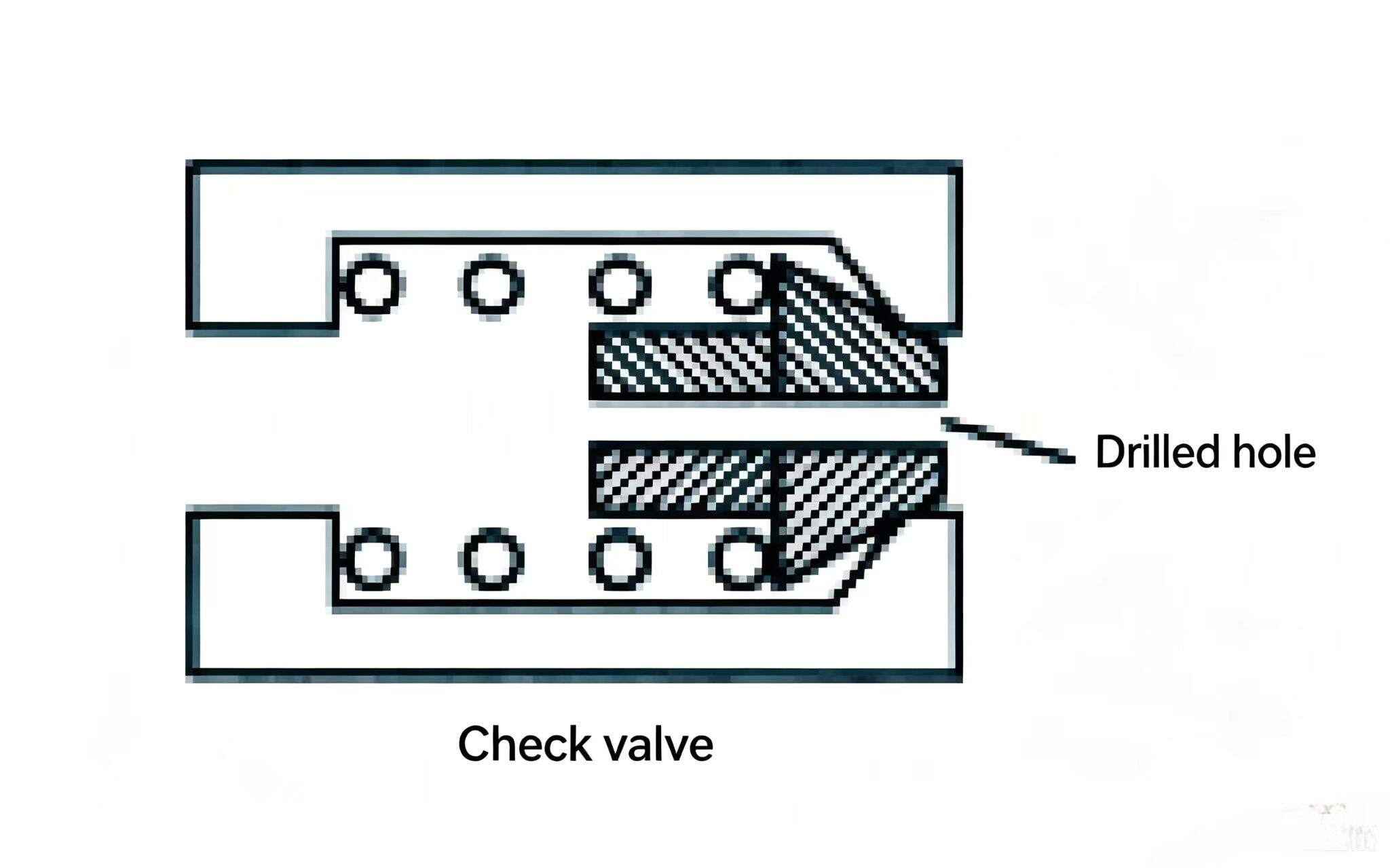
A fixed orifice has an opening size that cannot be adjusted. The most common examples in hydraulic technology are the drilled hole in a pipe plug or check valve, or the factory-preset flow control valve.
Most of the time a variable orifice is needed instead of a fixed one, because it is more adaptable. Gate valves, ball valves, and needle valves are all examples of variable orifices.
A gate valve has a straight-through flow passage. The size of the orifice is changed by rotating the handle to open or close the gate in the flow path. Although gate valves are not designed for flow control, in some rough flow-metering systems they can be used as flow restriction devices.
Ball valve flow passages are not straight — they make a 90° turn. The orifice is the seat and conical plug or ball plug on the turning passage. The orifice opening size is adjusted by changing the position of the ball plug.
Flow through needle valves also makes a 90° turn, then passes through an orifice. This orifice consists of the gap between a tapered-end valve rod and the valve seat. The size of the orifice is changed by adjusting the position of the cone face relative to the valve seat. Because the adjustment threads on the valve rod are fine-pitch and the tip is tapered, this orifice size changes gradually. In hydraulic systems, the needle valve is the most frequently used variable orifice.
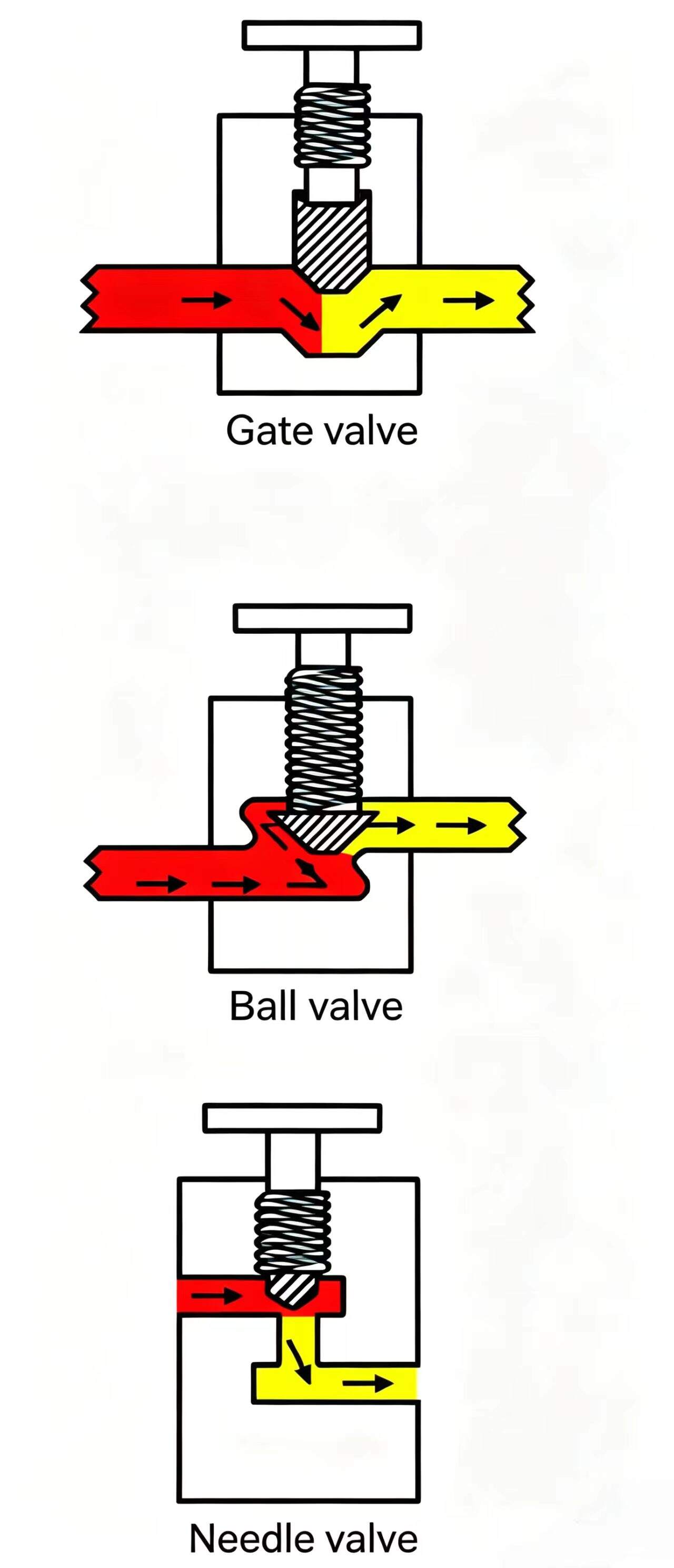
Figure 9-2 Variable orifice types. The needle valve (bottom) is the most common in hydraulics — its tapered tip and fine threads allow very precise, gradual flow adjustment.
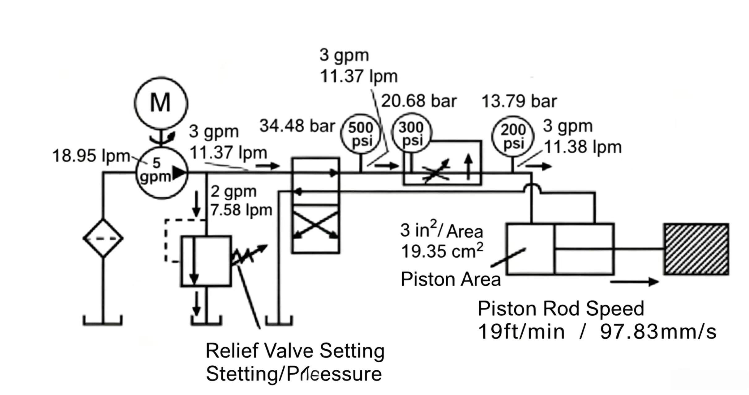
The example circuit uses a 5 gpm (18.95 Lpm) positive-displacement pump, a relief valve, a directional valve, a variable orifice (needle valve), and a hydraulic cylinder with 3 in² (19.35 cm²) piston area. If the relief valve is set at 500 psi (34.48 bar) and the pump delivers 5 gpm:
Rod speed (ft/min) = gpm x 231 / (piston area (in^2) x 12)
Rod speed (m/min) = Lpm x 10 / piston area (cm^2)
With the needle valve restricting flow to only 2 gpm (7.58 lpm), rod speed = 2 × 19.25 / 3 = 13 ft/min (3.96 m/min). The relief valve limits system pressure to 500 psi (34.48 bar) by routing the remaining 3 gpm (11.37 lpm) to tank.
Turning the needle valve out increases the orifice — more flow passes through to the cylinder, up to the relief valve pressure limit. Rod speed increases.
Turning the needle valve in reduces the orifice. Less flow enters the cylinder, so rod speed decreases.
Flow through an orifice is affected by the pressure differential. Because pressure is potential energy in a hydraulic system, the greater the pressure differential across an orifice, the more flow through it.
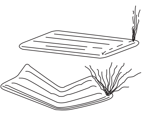
After a day at the beach or campsite, you remove the plug from an inflated air mattress and let air exhaust freely. Because the internal/external pressure differential is small, the mattress slowly collapses. Squeeze the mattress hard — the internal pressure rises relative to atmospheric pressure, the differential increases, and air flows out faster.
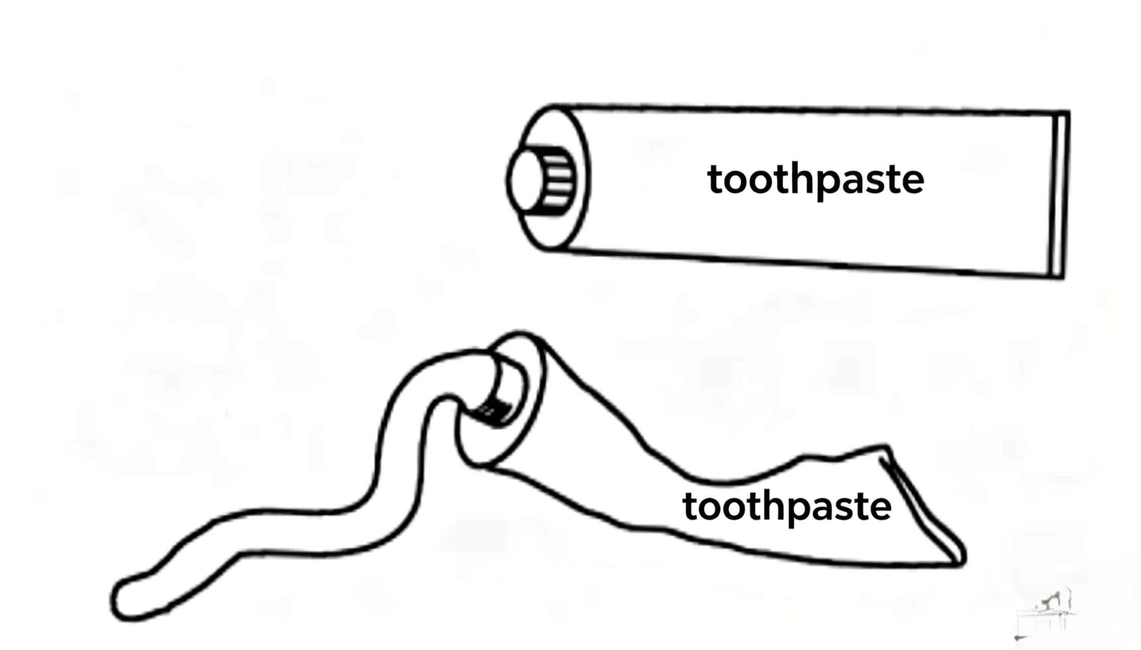
Gently squeeze a tube of toothpaste — a small amount comes out. Squeeze hard — more toothpaste is forced out and may land on the floor. If the toothpaste tube is stepped on, from inside to atmospheric pressure differential is greater than when squeezed by hand, so more toothpaste exits faster.
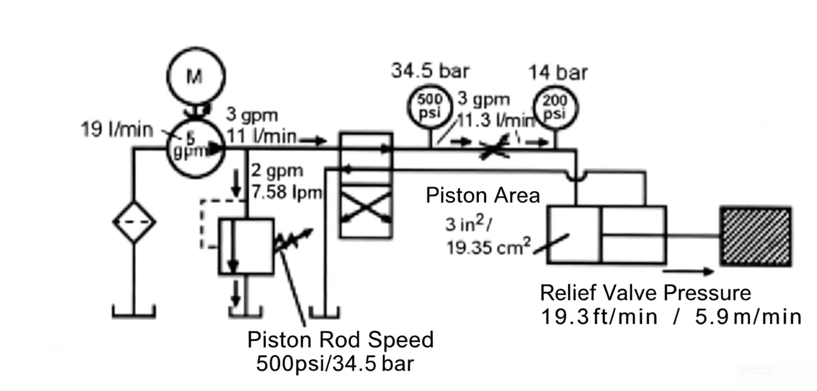
In the circuit shown, the needle valve limits 5 gpm (18.95 Lpm) pump flow to 3 gpm (11.37 Lpm). Relief valve setting 500 psi (34.48 bar). Load resistance 200 psi (14 bar). The needle valve inlet pressure equals the relief valve setting: 500 psi (34.48 bar). Of these 500 psi (34.48 bar), 200 psi (14 bar) overcomes load resistance; the remaining 300 psi (21 bar) pressure differential drives 3 gpm (11.3 lpm) through the needle valve, producing rod speed 19.25 ft/min (5.87 m/min). The remaining 2 gpm (7.58 lpm) goes through the relief valve to tank.
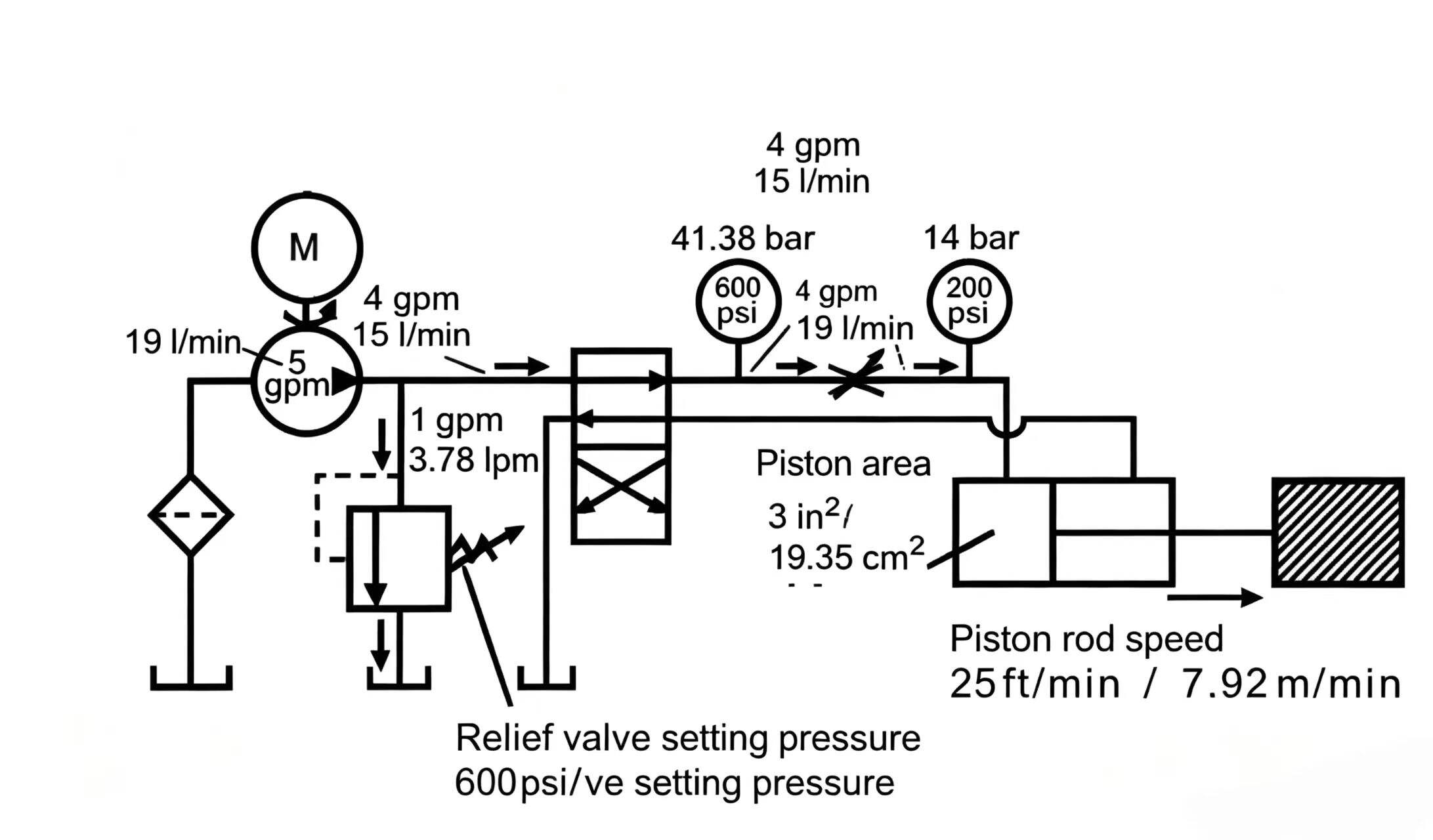
Keeping load pressure and needle valve setting unchanged, raising the relief valve to 600 psi (41.38 bar): needle valve inlet pressure becomes 600 psi (41.38 bar). Of these, 200 psi (14 bar) overcomes load; 400 psi (28 bar) pressure differential now drives 4 gpm (15 lpm) through the needle valve. Rod speed rises to 26 ft/min (7.92 m/min).

Reset relief valve back to 500 psi (34.48 bar) with needle valve unchanged. Load increases: load pressure rises to 400 psi (28 bar). Needle valve inlet pressure is still 500 psi (34.48 bar), but now only 100 psi (6.9 bar) differential drives flow through the needle valve — only 1 gpm (3.79 lpm). Rod speed drops to 6 ft/min (30 mm/s). The remaining 4 gpm (15 lpm) goes over the relief valve.
This demonstrates that flow through a needle valve changes with any pressure variation on either side of the orifice. To precisely meter flow through a needle valve, these pressure changes must be cancelled, or compensated.
From the examples above, any pressure change on either side of the orifice affects needle valve flow, changing actuator speed. To precisely meter flow through an orifice regardless of pressure variation, these pressure variations must be compensated. A needle valve is a non-compensated flow control valve — it is a good flow metering device as long as the pressure differential remains constant and the needle is well centered. For more precise flow control, a pressure-compensated flow control valve (speed control valve) should be used. This is a flow controller that compensates for pressure changes upstream and downstream of the orifice.
Speed control valves (pressure-compensated flow control valves) can be divided into meter-in type and bypass type.
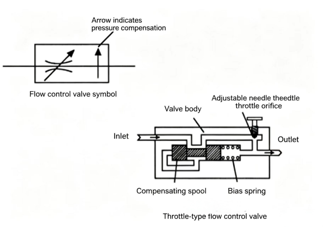
The meter-in pressure-compensated flow control valve consists of a valve body with inlet and outlet ports, a needle valve, a compensating spool, and a bias spring.
To understand how the meter-in type works, we analyze its operation step by step. When the compensating spool is fully shifted to side A, all incoming pressure oil reaches the needle valve orifice. As long as the compensating spool moves slightly toward side B, incoming pressure oil is throttled. To keep the flow passage open, the compensating spool is spring-biased toward side A. The needle valve inlet pressure is sensed through an internal control passage to the A-end of the compensating spool — when pressure rises above the spring bias force, the spool shifts toward side B.
If the needle valve orifice is adjusted so that less than the full pump flow passes through it, needle valve inlet pressure rises to the relief valve setting. When needle valve inlet pressure rises above the compensating spool spring force, the compensating spool shifts toward B, throttling incoming flow. When flow through the compensating spool orifice equals the pump's output flow, the needle valve inlet pressure stabilizes at the spring pressure value. For example, with a 100 psi (6.89 bar) spring value and relief set at 500 psi (34.48 bar): inlet pressure is 500 psi (34.48 bar); as oil flows through the compensating spool orifice, 400 psi (28 bar) converts to heat, dropping needle valve inlet pressure to 100 psi (6.89 bar). This means regardless of flow control valve inlet pressure, due to the compensating spool action, the needle valve inlet pressure is held at 100 psi (6.89 bar).
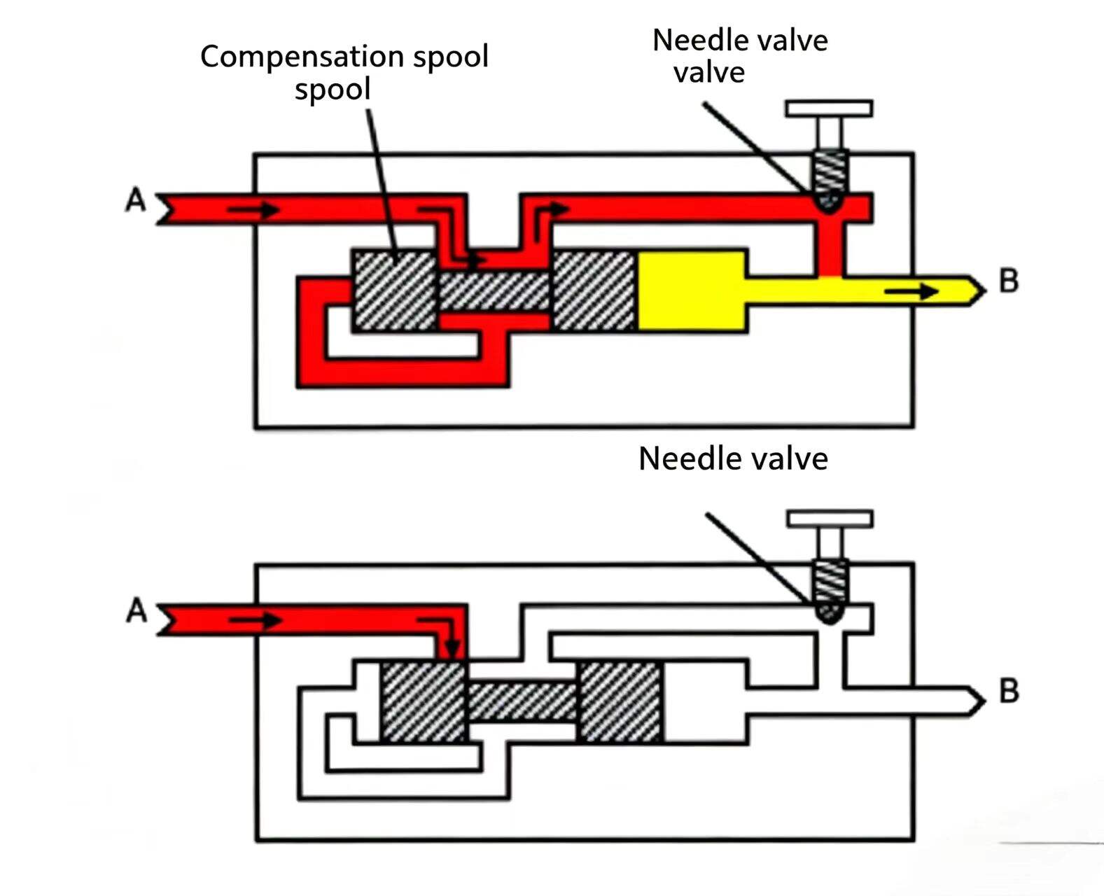
Figure 9-5 Meter-in speed control valve (pressure-compensated). The compensating spool holds the pressure drop across the needle valve constant regardless of inlet or outlet pressure changes — delivering a precise, constant flow.
For the earlier needle-valve circuit, the pressure differential across the needle valve orifice is only half the story — the pressure downstream of the needle valve must also be compensated. In other words, a constant pressure differential must be maintained. To achieve this, downstream pressure of the needle valve is also routed through a control passage to the compensating spool bias spring cavity. Now two forces act on the compensating spool A side: spring force and downstream oil pressure.
If spring force = 100 psi (6.89 bar), needle valve pressure differential will be limited to higher than downstream pressure by 100 psi (6.89 bar). As long as the relief valve is set high enough, the needle orifice pressure differential always equals the spring pressure value. By doing this, the pressure differential forcing flow through the needle valve is constant — not affected by upstream or downstream pressure fluctuations.
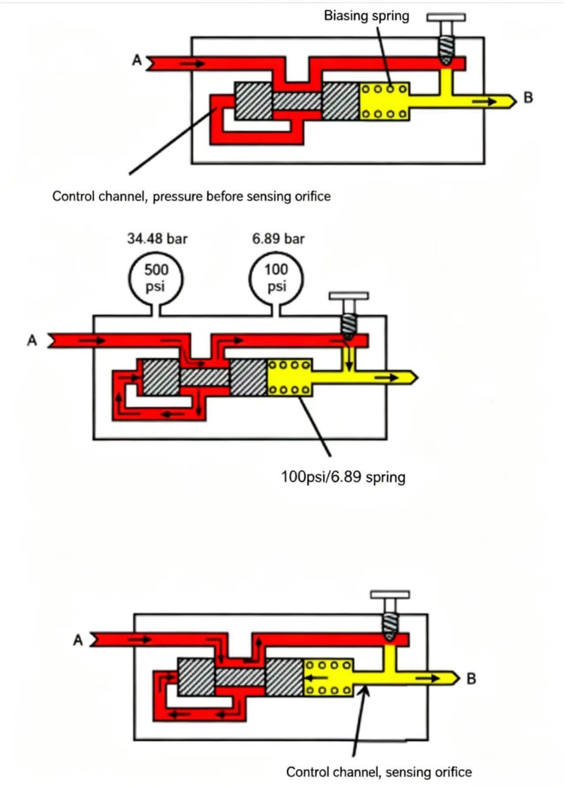
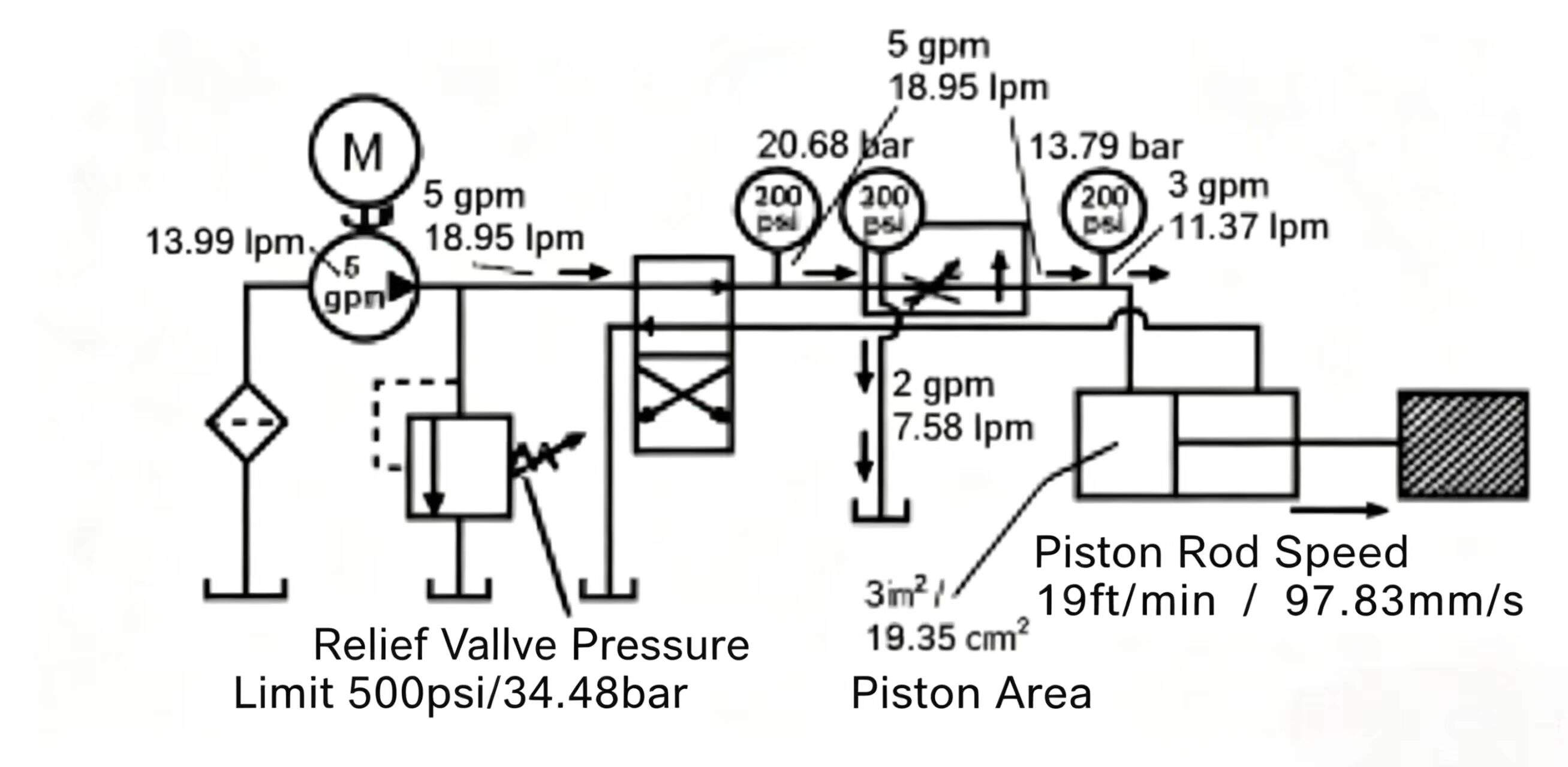
In the circuit, meter-in speed control valve set at 3 gpm (11.37 Lpm). Relief valve 500 psi (34.48 bar), load pressure 200 psi (13.79 bar). Compensating spool spring = 100 psi (6.89 bar). The pump tries to drive all 5 gpm (18.95 lpm) through the needle valve, causing needle valve inlet pressure to rise. At 300 psi (21 bar), the compensating spool shifts and throttles the flow, making the flow control inlet pressure rise to the relief valve setting 500 psi (34.48 bar). Of these 500 psi (34.48 bar), 200 psi (13.79 bar) is used to overcome load; 100 psi (6.89 bar) drives flow through needle valve; the remaining 200 psi (13.79 bar) in the 500 psi converts to heat as flow passes through the compensating spool orifice. The flow here is 3 gpm (11.37 Lpm) and rod speed = 19 ft/min (97.83 mm/s).
If load pressure rises to 400 psi (27.58 bar) or relief is reset to 600 psi (41.38 bar), there is still 100 psi (6.89 bar) driving flow through the needle valve. As long as relief is set high enough to move the compensating spool, output flow to the cylinder will be a constant 3 gpm (11.37 Lpm).
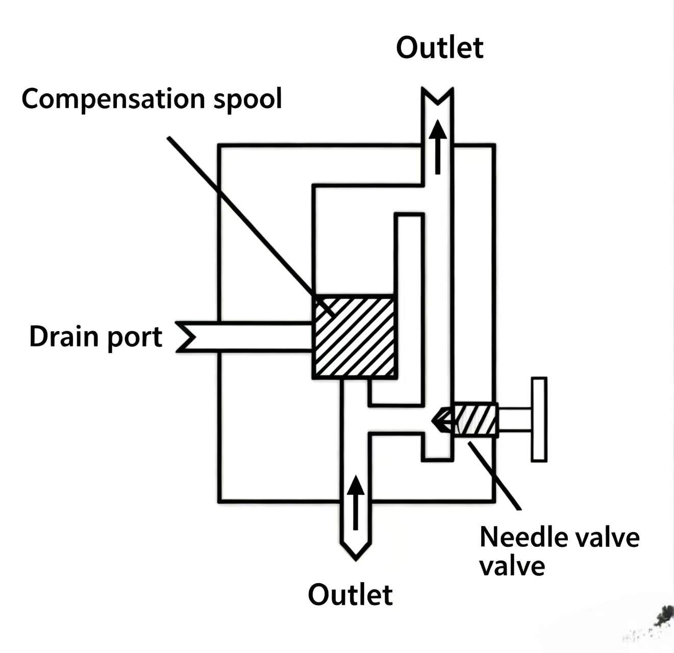
The bypass-type speed control valve consists of a valve body with inlet, outlet, and return ports, a needle valve, a compensating spool, and a bias spring.
The compensating spool in this valve opens and closes a bypass passage to the tank return. The compensating spool is spring-biased to close (lower position). If the spring has 100 psi (6.89 bar) force value, needle valve inlet pressure will be limited to 100 psi (6.89 bar). When flow through the valve is fully sent to the oil tank in its initial state. Under normal operation, the compensating spool is spring-biased at the closed position.
Needle valve inlet pressure is sensed through an internal control passage to the top of the compensating spool. When pressure rises above the spring bias force, the compensating spool acts like a relief valve — opening the bypass passage, limiting needle valve inlet pressure at 100 psi (6.89 bar). The needle valve fixed inlet pressure does not ensure constant flow — if downstream pressure changes, the needle orifice pressure differential changes, and flow changes.
To compensate for this, downstream needle valve pressure is routed through a control passage to the compensating spool bias spring cavity. Now the compensating spool A-side has two bias forces: spring force and downstream oil pressure. If spring = 100 psi (6.89 bar), needle inlet pressure will be limited to 100 psi (6.89 bar) above downstream pressure. As long as the relief valve is set high enough, needle orifice pressure differential equals 100 psi (6.89 bar) — constant.
Bypass-type speed control valve set at 3 gpm (11.37 Lpm). Relief 500 psi (34.48 bar), load 200 psi (13.79 bar), spring = 100 psi (6.89 bar). The pump tries to drive all 5 gpm (18.95 Lpm) through the needle valve. The compensating spool opens the bypass passage, limiting needle valve inlet pressure at 300 psi (20.68 bar). Of this 300 psi: 200 psi (13.79 bar) overcomes load, 100 psi (6.89 bar) drives 3 gpm (11.37 Lpm) through needle. The remaining 2 gpm (7.58 Lpm) bypasses through the compensating spool opening back to tank.
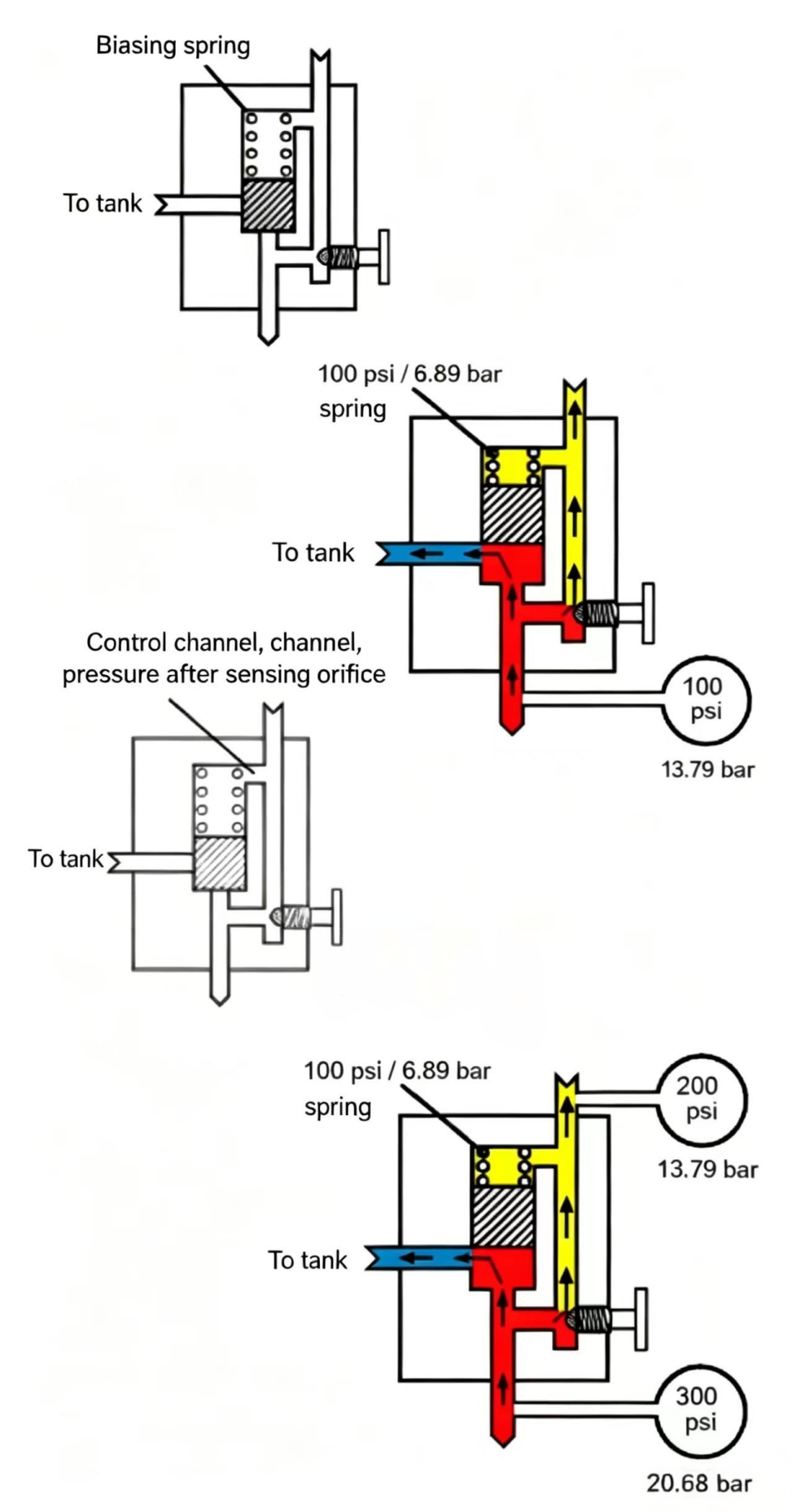
Figure 9-8 Bypass-type speed control circuit. The compensating spool bypasses excess pump flow directly to tank rather than sending it over the relief valve. This is more energy-efficient than the meter-in type because the excess flow does not travel through the full system pressure.
If load pressure rises to 400 psi (27.58 bar) or relief is reset to 600 psi (41.38 bar), there is still 100 psi (6.89 bar) pushing flow through the needle valve. As long as the relief is set high enough to open the compensating spool, output to the cylinder is a constant 3 gpm (11.37 Lpm).

As mentioned at the start of this chapter, the three main factors affecting orifice flow are orifice size, pressure differential, and oil temperature. When oil temperature changes, its viscosity changes — when oil viscosity changes, orifice flow also changes. For fixed orifices or needle valves, temperature-induced flow changes are usually not significant because orifice size and pressure differential are generally large relative to viscosity effects. However, for applications requiring very precise flow control, temperature effects must be considered. Both meter-in and bypass-type speed control valves are generally adequate for typical industrial hydraulic applications.
For applications requiring extremely precise flow control — regardless of temperature changes — a temperature-compensated flow control valve can be used. This type also compensates for temperature effects.
|
Concept |
Formula |
Notes |
|
Rod speed with flow control |
v = Q_controlled x 19.25 / A |
Q_controlled = flow through needle, A = piston area in in^2 |
|
Orifice pressure drop |
dP across needle = spring value |
Held constant by compensating spool |
|
Excess pump flow |
Q_excess = Q_pump - Q_controlled |
Goes over relief valve (meter-in) or bypass spool (bypass type) |
|
Key difference |
Meter-in: excess over relief valve |
Bypass type: excess through spool direct to tank — more efficient |

Welcome to HOVOO, a Chinese seal factory. Production of PU, Rubber and PTFE seals. The seals include O-ring, piston seal, rod seal, Gray ring and gas seal.


 EN
EN
 AR
AR CS
CS DA
DA NL
NL FI
FI FR
FR DE
DE EL
EL IT
IT JA
JA KO
KO NO
NO PL
PL PT
PT RO
RO RU
RU ES
ES SV
SV TL
TL IW
IW ID
ID LV
LV SR
SR SK
SK VI
VI HU
HU MT
MT TH
TH TR
TR FA
FA MS
MS GA
GA CY
CY IS
IS KA
KA UR
UR LA
LA TA
TA MY
MY