33-99No. Mufu E Rd. Gulou Bezirk, Nanjing, China [email protected] | [email protected]
33-99No. Mufu E Rd. Gulou Bezirk, Nanjing, China [email protected] | [email protected]

Die Konstruktion eines hydraulischen Felsbrechers bedeutet die Berechnung der konstruktiven Parameter, die die in der Konstruktionsspezifikation festgelegten Leistungsanforderungen erfüllen. Unter diesen konstruktiven Parametern kann der hydraulische Felsbrecher die erforderliche Schlagenergie und Schlagfrequenz erreichen.
Es muss nachdrücklich betont werden, dass der hydraulische Felsbrecher die Schlagenergie und Schlagfrequenz durch die Hin- und Herbewegung des Kolbens innerhalb einer festen Hublänge erzeugt. S innerhalb des Zylinderkörpers. Bei diesem festen Hub bewegt sich der Kolben in einem kontinuierlichen Zyklus: Beschleunigung im Rückhub → Verzögerung im Rückhub (Bremsen) → Geschwindigkeit im Rückhub sinkt auf null → Beschleunigung im Arbeitshub → erreicht den Schlagpunkt mit maximaler Geschwindigkeit v m → trifft auf das Meißelende (überträgt Schlagenergie) → bleibt stehen und beginnt den nächsten Zyklus. Dieser feste Hub S wird als Kolbenhub bezeichnet; er stellt eine wichtige Grundlage für die Bestimmung der Abmessungen des Zylinderkörpers dar.
Der Kolben bewegt sich hin und her innerhalb des Zylinderkörpers. Ausgehend vom Schlagpunkt beschleunigt er im Rückhub, um die maximale Rückhubgeschwindigkeit zu erreichen v mo , anschließend beginnt er aufgrund des Ventilwechsels zu verzögern; die Geschwindigkeit sinkt schnell von v mo auf null — der Kolben bleibt im oberen Totpunkt stehen. Der Hub, den der Kolben zurücklegt, wird als Rückhub bezeichnet. Zu diesem Zeitpunkt beginnt der Kolben aufgrund des Ventils, das sich noch in seinem ursprünglichen Zustand befindet, auf dem Arbeitshub zu beschleunigen, bis er den Stoßpunkt erreicht. Wenn der Kolben mit dem Meißelschaft in Kontakt kommt, hat seine Geschwindigkeit ihren Maximalwert erreicht — dies wird als maximale Schlaggeschwindigkeit des Kolbens bezeichnet v m . Der Hub, den der Kolben vom oberen Totpunkt bis zum Kontakt mit dem Meißelschaft zurücklegt, wird als Arbeitshub bezeichnet. Offensichtlich müssen Rückhub und Arbeitshub gleich sein.
Um die Konstruktionstheorie hydraulischer Felsbrecher tiefer zu verstehen, ist es hilfreich, zunächst die Kolbengeschwindigkeit, die verschiedenen Kammerdrücke sowie die Verteilung und Veränderung des Durchflusses während des Betriebs zu analysieren. Die Gründe für die Änderungen der Betriebsparameter eines hydraulischen Felsbrechers während des Betriebs sowie deren Richtung sind in Abb. 2-4 dargestellt. 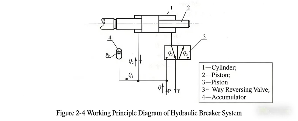
p 0ist der Stickstoff-Vorladedruck des Speichers; Q ist der vom Pumpenstrom an den hydraulischen Felsbrecher gelieferte Durchfluss; Q 1ist der Speicher-Ansaugstrom (+) und -Auslassstrom (−); Q 2ist der Ansaugstrom (+) und Auslassstrom (−) der Kolbenvorderkammer mit Q = Q 1 + Q 2. Q 3ist der Ansaugstrom (+) und Auslassstrom (−) der Kolbenhinterkammer; p ist der Systemdruck.
Abb. 2-4 zeigt den Kolben zu Beginn des Rückhubes. Der Pumpenstrom Q tritt in das System ein; ein Teil ( Q 2) tritt in die Kolbenvorderkammer ein und treibt deren Rückhub, während die Hinterkammer Öl in den Tank entlässt ( Q 3); der andere Teil ( Q 1) tritt in den Speicher ein und verdichtet den Stickstoff, sodass der Systemdruck p vom Vorladedruck des Speichers ausgeht p 0und steigt kontinuierlich an, während Q 1einströmt. Die Bewegung des hydraulischen Felsbrechers, basierend auf dem Arbeitszustand des Kolbens, lässt sich allgemein in drei Phasen unterteilen, die wie folgt beschrieben werden:
(1) Kolben-Rückhubbeschleunigung
Der Kolben beginnt den Rückhub vom Auftreffpunkt aus. Während die Pumpe kontinuierlich Öl fördert, steigt der Systemdruck p ↑ → Kolbengeschwindigkeit v ↑ → Q 2↑ → Q 1↓ → Q 3↑, und Öl wird weiterhin in den Tank abgeleitet. Da die Kolbengeschwindigkeit v ↑ → Q 2↑ → Q 1↓, bis Q 1= 0 ist. Das Kennzeichen dieser Phase ist v ↑ und p ↑. Wenn Q 1= 0 ist, tritt ein Wendepunkt auf: Der Druck p steigt nicht mehr an, doch die Kolbengeschwindigkeit nimmt weiter zu (da die treibende Kraft für den Kolben-Rückhub nach wie vor vorhanden ist). Nach diesem Wendepunkt steigt aufgrund von v ↑ der Pumpendurchsatz Q nicht mehr aus, um den Durchsatzbedarf für die Kolbenbewegung zu decken, d. h. Q 2 > Q um den Durchsatzbedarf der vorderen Kolbenkammer zu decken, muss der Speicher nun Öl abgeben, um die Unterversorgung der Pumpe auszugleichen. Auf Grundlage des Durchsatzbilanzprinzips gilt: Q 2 = Q + Q 1; zu diesem Zeitpunkt Q 1ist der Durchsatz, der aus dem Speicher austritt und in die vordere Kolbenkammer eintritt, bis v ↑ zu v = v mo , schaltet das Ventil um, und der Kolben tritt in die Verzögerungsphase des Rückhubes ein.
(2) Kolben-Rückhub-Verzögerung
Während des Rückhubes hat die vordere Schulter des Kolbens das Rückführloch bereits passiert; dadurch schaltet das Ventil um und kehrt die Kraftwirkungsrichtung am Kolben um. Die Antriebskraft wirkt nun in umgekehrter Richtung auf den Kolben, sodass dieser zu verzögern beginnt, bis v = 0. Der Rückhub ist damit abgeschlossen; der Kolben hat den oberen Totpunkt erreicht und den gesamten Hub zurückgelegt S , und ist bereit, den Arbeitshub zu beginnen.
(3) Kolben-Arbeitshub
Wenn die Kolbengeschwindigkeit auf v = 0 sinkt, kehrt sich die am Kolben wirkende Kraft um, wodurch sich auch die Kolbengeschwindigkeit v umkehrt und von „+“ auf „−“ wechselt. Der Kolben beginnt dann unter der umgekehrten Kraft mit der Beschleunigung im Arbeitshub. Zu Beginn der Beschleunigung im Arbeitshub startet die Kolbengeschwindigkeit von v = 0 ausgehend, zu diesem Zeitpunkt beträgt der Kolbenölverbrauch Q 3= 0; die gesamte Pumpenfördermenge Q fließt in den Speicherbehälter ein, Q 1 = Q , Q 2= 0. Da die Geschwindigkeit des Arbeitshubs v ↑ → Q 3↑ → Q 1↓ → Q 2(−)↑. Hier ist zu beachten, dass aufgrund des kleineren Kolbenvorderkammerquerschnitts Ein 2im Vergleich zum Kolbenhinterkammerquerschnitt Ein 1, gemäß dem Prinzip der Strömungsbilanz, folgen muss: Q 3 = Q 2 + Q − Q 1, mit v ↑ und Q 1↓, bis Q 1= 0. Dies bedeutet, dass v ↑; zu diesem Zeitpunkt wird die gesamte Pumpenfördermenge Q vollständig in die Kolbenhinterkammer eingespritzt, d. h. Q 3 = Q , Q 1= 0, jedoch die Kolbengeschwindigkeit v hat noch nicht die maximale Geschwindigkeit erreicht v m der Kolben beschleunigt weiter; der Pumpendurchsatz Q kann die Nachfrage nicht mehr decken, daher beginnt der Speicher, den Durchsatz zu ergänzen, d. h. Q 3 = Q + Q 1(−), bis der Kolben mit maximaler Geschwindigkeit auf das Meißelende trifft v m im Moment des Aufpralls wird die Kolbengeschwindigkeit plötzlich v = 0, und der Kolben gibt Stoßenergie W nach außen ab und schließt damit einen Arbeitszyklus ab.
Da sich der Ein-/Auslassstrom des Speichers Q 1ändert, ändert sich auch der Systemdruck p entsprechend. Beim Aufladen des Speichers, Q 1= '+', Systemdruck p ↑; wenn der Speicher nach außen entlädt, Q 1= '−', Systemdruck p ↓. Mit anderen Worten begleiten Systemdruckschwankungen stets den Arbeitsprozess eines hydraulischen Felsbrechers. Wenn der Speicher mit der maximalen Ölmenge gefüllt ist, befindet sich der Systemdruck auf seinem höchsten Wert. Wenn der Kolben den Schlagpunkt erreicht hat, hat der Speicher die größte Ölmenge abgegeben – dies ist der Zeitpunkt des niedrigsten Systemdrucks. Daher oszilliert der Systemarbeitsdruck eines hydraulischen Felsbrechers von dessen Inbetriebnahme bis zum Erreichen des stationären Betriebs stets zwischen einem maximalen Druck p und einem minimalen Druck p max und ein Mindestdruck p min , und es ist absolut unmöglich, dass er konstant und unverändert bleibt. Abb. 2-5 zeigt die Variation aller Systemparameter während des Betriebs des hydraulischen Felsbrechers. 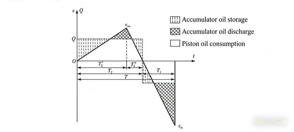
Abb. 2-5 Verlauf der Systemparameter während des Betriebs eines hydraulischen Felsbrechers [Legende: schraffiert = Akkumulatoraufladung; punktiert-schraffiert = Akkumulatorentladung; weiß = Kolbenölverbrauch]
Der oben beschriebene Arbeitsprozess zeigt, dass die Variation der Arbeitsparameter äußerst komplex ist – es handelt sich um ein nichtlineares System. Dies erschwert eine tiefgreifende theoretische Analyse und Forschung erheblich. Tatsächlich ist dies einer der Hauptgründe dafür, dass die theoretische Forschung zu hydraulischen Felsbrechern hinter der Produktentwicklung zurückgeblieben ist.
Forscher weltweit verfolgen im Allgemeinen zwei unterschiedliche technische Ansätze für die theoretische Forschung an hydraulischen Schlaggeräten (hydraulischen Felsbrechern): Forschung auf der Grundlage der linearen Systemtheorie und Forschung auf der Grundlage der nichtlinearen Systemtheorie.
1) Die auf der linearen Systemtheorie beruhende Forschung geht davon aus, dass die Kraft auf den Kolben konstant ist, die Kolbengeschwindigkeit linear mit einer gleichmäßigen Rate ansteigt und bestimmte Einflussfaktoren vernachlässigt werden; auf dieser Grundlage wird ein lineares mathematisches Modell für theoretische Untersuchungen erstellt. Diese Forschungsmethode ist zweifellos einfach und kann einige praktische Probleme lösen, weist jedoch nur eine geringe Genauigkeit auf und führt zu erheblichen Fehlern.
2) Die auf der nichtlinearen Systemtheorie beruhende Forschung beschreibt die Bewegungsmuster des hydraulischen Felsbrechers mittels hochgradiger nichtlinearer Differentialgleichungen und stellt die Kinematik und Dynamik des hydraulischen Felsbrecherkolbens genauer dar. Diese nichtlineare Forschung ist genauer als die lineare Forschung, stützt sich jedoch nach wie vor auf einige Annahmen. Zwar kann sie physikalische Phänomene des hydraulischen Schlages genauer aufzeigen, doch ist sie schwer zu lösen, kaum interpretierbar und liefert lediglich numerische Lösungen durch Computerberechnung, was ihre Anwendung erschwert.
Neben diesen beiden Ansätzen schlugen die Autoren nach jahrelanger intensiver Forschung die Theorie des abstrakten Variablendesigns für hydraulische Gesteinsbrecher (hydraulische Schlagmechanismen) vor. Mithilfe der Theorie des abstrakten Variablendesigns lassen sich analytische Lösungen für hydraulische Gesteinsbrecher finden, die die inneren Bewegungsmuster hydraulischer Gesteinsbrecher tiefgreifend aufdecken und eine theoretische Grundlage für technische Innovationen durch Anwender liefern.
Der Forschungsansatz der Theorie zum abstrakten Variablenentwurf hydraulischer Felsbrecher: Anerkennung der Nichtlinearität der Betriebsparameter hydraulischer Felsbrecher, jedoch unter Verwendung einer äquivalenten Krafttransformation, um das nichtlineare System zu linearisieren, sodass es mit Methoden der linearen Systemtheorie untersucht und analytische Lösungen ermittelt werden können. Die mit dieser Methode ermittelten Betriebs- und Konstruktionsparameter hydraulischer Felsbrecher sind sehr genau und die Berechnung ist einfach. Die Theorie zum abstrakten Variablenentwurf hydraulischer Felsbrecher wird in den folgenden Kapiteln ausführlich behandelt.

Willkommen bei HOVOO, einer chinesischen Dichtungsfabrik. Produktion von PU-, Gummis- und PTFE-Dichtungen. Die Dichtungen umfassen O-Ring, Kolben-Dichtung, Stange-Dichtung, Grau-Ring und Gas-Dichtung.


 EN
EN
 AR
AR CS
CS DA
DA NL
NL FI
FI FR
FR DE
DE EL
EL IT
IT JA
JA KO
KO NO
NO PL
PL PT
PT RO
RO RU
RU ES
ES SV
SV TL
TL IW
IW ID
ID LV
LV SR
SR SK
SK VI
VI HU
HU MT
MT TH
TH TR
TR FA
FA MS
MS GA
GA CY
CY IS
IS KA
KA UR
UR LA
LA TA
TA MY
MY