33-99No. Mufu E Rd. Gulou District, Nanjing, China [email protected] | [email protected]
33-99No. Mufu E Rd. Gulou District, Nanjing, China [email protected] | [email protected]

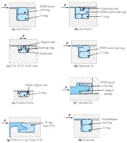
Dynamic O-ring seals balance sealing force, friction, lubricating film, leakage, and service life. Static seals mainly focus on whether contact stress is maintained over the long term after compression; dynamic seals must also handle relative motion, so breakout force, running friction, stick-slip/creep, heat generation, wear, and lubricating-film breakdown all come into play.
An O-ring must be compressed enough to seal, but the tighter the compression, the greater the friction and wear.
The Parker O-Ring Handbook groups the primary factors affecting dynamic seal friction into three categories: sealing-part factors (geometric shape, manufacturing tolerance, pre-compression, material hardness, dry/wet friction coefficient, swell and low-temperature behavior); media factors (lubricant film formation, viscosity and its temperature dependence); and operating-condition factors (working pressure, friction speed, mating metal surface roughness, machining tolerance, piston-shaft radial load and lead-in conditions).
Dynamic O-ring friction can be simplified as: Ff ≈ μ × N, where N ≈ N(compression pre-load) + N(media pressure) + N(misalignment/lead-in). In other words, friction is not determined by material alone — it is jointly determined by the friction coefficient μ and the contact force N.
After the O-ring is installed into the groove, it is compressed radially or axially, producing initial sealing contact pressure. This pressure is beneficial for a static seal, but becomes a friction source in a dynamic seal. The larger the compression amount, the larger the contact area, and the higher the sealing line pressure — startup and running friction generally both rise. Parker's low-friction parameter table also clearly lists "reduce O-ring compression, reduce cross-section, reduce hardness, reduce pressure, use lubrication, reduce running surface roughness" as directions to lower friction. However, there is an engineering trade-off here: too little compression risks leakage; too much compression brings higher breakout force, heat, and wear.
In hydraulic cylinders, pneumatic cylinders, and actuators, the O-ring is not simply installed under compression — system pressure further pushes the O-ring toward the sealing face, increasing contact pressure. For O-rings, friction typically rises as pressure increases; the Parker handbook also notes O-ring friction rises with working pressure. Therefore, a common issue in high-pressure hydraulic cylinders is: the higher the pressure, the more reliable the seal, but friction, heat, and wear also become more pronounced.
Rubber is not a rigid material but a viscoelastic material. During sliding contact it experiences surface adhesion, local elastic deformation, hysteresis loss, and micro-shear/compression-rebound lag. This means O-ring friction does not come only from surface "scraping" — it also comes from energy loss within the rubber body during the deform-recover cycle. Hardness, filler system, surface treatment, material polarity, and media compatibility all affect friction behavior.
Breakout force, also called breakout friction or static friction, is the problem dynamic-seal customers most easily notice, typically manifesting as: hydraulic cylinder pressure spikes at the instant of startup; pneumatic cylinder feels distinctly stuck on first motion; actuator positioning starts unevenly; the first motion after a shutdown period is especially heavy; servo systems show jitter or overshoot on positioning. The Parker handbook distinguishes "static friction that must be overcome when motion begins" from "dynamic friction during the motion process," and notes static friction is especially important in reciprocating or cylinder-type applications.
After the O-ring has been stationary for a period, the lubricating film between the contact surfaces is gradually squeezed out by the pre-compression, and the rubber and metal surfaces move closer to a friction or boundary-friction state. The longer the standstill time, the thinner the oil film and the more pronounced the adhesion, and the higher the breakout force. The Parker handbook points out that the elastomer's static break-out friction is typically significantly higher than dynamic friction; the longer the standstill time, the more easily oil is squeezed from the sealing contact face, and breakout friction can approach boundary-friction levels — even reaching several times the running friction.
Influencing Factor |
Effect on Breakout Force |
Excessive compression |
Higher contact pressure, higher breakout friction |
Groove too narrow |
O-ring cannot deform reasonably, abnormal contact pressure |
Material hardness bias |
High contact pressure, poor low-speed flexibility |
Sticky material surface |
Adheres to metal surface, worse after standstill |
Insufficient lubrication |
Higher proportion of boundary friction |
Long standstill time |
Oil film gets squeezed out, adhesion strengthens |
High temperature |
Media viscosity drops, oil film easily interrupted |
Surface too rough |
Cutting, wearing the O-ring |
Surface too smooth |
Especially in pneumatic applications, not conducive to retaining a lubricating film |
Rod/bore mismatch |
Local over-compression, local friction increase |
Running friction is the resistance the O-ring generates during continuous reciprocating motion. It directly affects cylinder efficiency, actuator response speed, low-speed stability, heat generation, seal life, energy consumption, and control precision. The difficulty of running friction: lower friction often means increased leakage risk; tighter sealing raises friction and wear. The Parker handbook also clearly notes reducing contact force raises leak risk, so low friction and high sealing capability often need to be traded off.
Friction State |
Characteristics |
Risk |
Boundary friction |
Very thin oil film, extensive rubber-metal micro-contact |
High breakout friction, wear |
Mixed friction |
Localized oil film, localized direct contact |
Common in dynamic seals |
Fluid lubrication |
Contact surfaces continuously separated by oil film |
Low friction, but higher leak risk |
The Parker handbook uses the Stribeck curve to describe sealing friction: from static startup it is typically in boundary friction, and leakage increases significantly as it enters mixed friction; pure fluid lubrication achieves relatively stable friction in the seal and continuous lubrication significantly reduces leak risk. In the handbook's typical description, the boundary friction coefficient is about 0.3, and mixed friction can drop to about 0.06–0.08, though the specific value depends on the lubrication ratio and operating condition.
At low reciprocating speed, a lubricating film is difficult to form, and friction stays in the boundary or mixed zone, making startup resistance, creep, and wear more likely. As speed rises, the lubricating film is more easily formed, and the friction coefficient may drop; the Parker handbook notes increased piston speed is generally favorable for lowering friction, since higher speed more easily forms an effective lubricating film — but absolute friction still depends on seal structure, material, pressure, and oil-film scraping degree. But speed is not the higher the better. At high speed, even as the friction coefficient drops, friction power can still rise: Pheat = Ff × v. So common problems in low-speed reciprocating conditions are fear of creep, and at high speed the fear is heat generation and wear.
Stick-slip, commonly called sticking-slipping, creep, jitter, or low-speed instability in Chinese, is not simply "large friction" — it is a dynamic phenomenon of friction force varying unstably with speed, superimposed with system elasticity.
Typical manifestations: pneumatic cylinder judders at low-speed running; hydraulic cylinder extends discontinuously at low speed; actuator positioning first gets stuck then suddenly jumps; servo cylinder micro-position control is unstable; periodic jitter occurs under low-speed, high-load conditions; occasional obvious impacts on reversal.
The Parker handbook gives three necessary conditions for stick-slip: static friction continuously exceeds dynamic friction; running speed is below the speed corresponding to the friction coefficient's low point; power is transmitted through an elastic body, as commonly seen in hydraulic cylinders with a compressible oil column.
In engineering terms: first it gets stuck, system pressure or elastic deformation keeps accumulating; once static friction is overcome, friction suddenly drops and the moving part rapidly darts forward; then speed drops, and it re-enters the stuck state. This is the "stuck-rush-stuck-rush" cycle.
At low speed, the lubricating film is insufficiently thick, and the sealing face is more often in the boundary friction zone. At this point static and dynamic friction differ greatly. Pneumatic systems are especially pronounced. The Parker handbook notes pneumatic seal lubrication conditions are less favorable than hydraulic seals; if grease lubrication is used, the lubricating film cannot be continuously replenished like oil supply, and gets gradually scraped away with reciprocating travel. For low-speed pneumatic cylinders, if speed is reduced by throttling the air supply, stick-slip risk is even higher; sharp seal edges and unsuitable metal surface roughness will also aggravate this problem.
Low speed itself is not the problem. The problem is insufficient lubricating-film formation at low speed, static friction much greater than dynamic friction, an unfavorable slope in the friction-speed curve, plus system elasticity. So when a customer says "pneumatic cylinder creeps at low speed," the answer cannot just be "add more grease." It's necessary to also check: is O-ring compression excessive; is the material biased hard or with a shiny surface; is the cylinder-bore surface too rough or too glossy; has it long lacked oil lubrication; is the piston rod off-center; does the air supply rely on severe throttling to achieve low speed; is the cylinder bore diameter large but the load small and uneven; is it necessary to switch to an X-ring, Y-ring, U-cup, or a low-friction combination seal.
Dynamic seals are neither completely dry friction nor reliant on a very thick oil film. The ideal state is usually a thin, stable, well-adhered lubricating film.
The Parker handbook notes the optimal state is a relatively thin lubricating film with sufficient adhesion; if the lubricating film is scraped away, sealing may still be very tight, but wear increases faster; if the lubricating film is too thick, it may cause undesirable leakage.
When the lubricating film is too thin: breakout force rises; stick-slip risk increases; rubber surface wear intensifies; local temperature rise increases; the O-ring contact area at the seal lip brightens and tears; the cylinder may develop squealing or jitter. Common causes include insufficient lubricant, low media viscosity, high temperature, unsuitable surface roughness, excessive pre-compression, and long standstill time.
When the lubricating film is too thick: friction may decrease, but oil increases at the rod surface; oil film gets carried out during reciprocating travel; external leakage or oil mist increases; the pneumatic system may contaminate the environment; the hydraulic cylinder may develop rod leakage. So "more lubrication is always better" does not hold — what dynamic seals need is a controllable oil film, not unlimited oil supply.
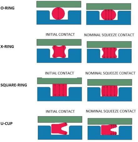
Friction heat generation can be understood with a simple relation: Pheat = Ff × v. At low speed, heat generated per unit time may not be high, but boundary friction and stick-slip are pronounced; at high speed, the friction coefficient may drop, but sliding speed is high, and the heat generation rate can still be large. Heat generation triggers a chain reaction: media viscosity drops (the Parker handbook also notes that under high-temperature, low-viscosity conditions, the lubricating film may further thin, and friction may increase further as lubrication is interrupted more easily), rubber softens or hardens (different materials — NBR, FKM, EPDM, HNBR — have different aging mechanisms under different media and temperature), compression set increases (seal rebound capability decreases, potential leakage later), wear increases (surface fatigue, particle shedding, scoring, cracking becomes more obvious), lubricant grease ages (especially in pneumatic or low-lubrication systems), and system control worsens (friction drifts with temperature, causing response drift in servo and precision actuators). For customers, heat generation is not an isolated fault — it is the joint result of an imbalance among friction, lubrication, material, speed, and pressure.
O-rings used in reciprocating dynamic seals typically wear out earlier than static seals do. The Parker handbook notes friction causes wear; wear is difficult to precisely predict, but it directly determines O-ring seal life and maintenance frequency. Sealing parts in many operating conditions are not actually long-term reliant on fluid lubrication, but instead operate in the mixed friction zone, so wear resistance largely depends on material, media lubricity, and mating surface roughness.
Wear/Failure Type |
Appearance |
Common Cause |
Uniform wear |
Contact face becomes flat and shiny |
Normal dynamic wear, excessive compression |
Scoring wear |
Surface with directional scratches |
Rough rod/cylinder surface, particle contamination, lack of oil |
Adhesive wear |
Surface sticky, localized tearing |
High temperature, incompatible material and media, high friction |
Fatigue wear |
Surface cracking, particles shedding |
High-speed reciprocating, pulsating pressure, material fatigue |
Extrusion nibbling |
Edge worn away, burred |
Excessive clearance, high pressure, insufficient hardness |
Spiral twisting |
O-ring twisted, localized curling |
Poor groove design, poor lubrication, unstable direction |
Thermal aging wear |
Hardening, cracking, embrittlement |
Long-term high temperature, friction heat, media attack |
For hydraulic cylinder and pneumatic cylinder customers, the most critical distinction: is it a sealing-material shortfall, or has the system's surface, lubrication, or guiding condition caused the wear? Many after-sales issues are not that the O-ring material itself is "bad" — it's that the dynamic seal operating condition has already exceeded the applicable envelope of a general O-ring.
The dynamic seal mating face cannot be judged by Ra alone. Surface peak-valley shape, load-bearing area, and machining method all matter. The Parker handbook notes that dynamic seal mating faces generally require a finer finish than static seal faces, recommending a mating-surface roughness reference of Rt ≤ 2.5 μm, Ra 0.25–0.5 μm, while also considering load-bearing area and peak shape; grinding, drawing, and similar cold-working surfaces should have no sharp peaks, and the valleys can serve as potential lubricant reservoirs, helping improve dynamic sealing behavior.
A surface that is too rough will: cut the rubber; destabilize the oil film; increase the proportion of mixed friction; increase abrasive wear; shorten seal life.
A surface that is too smooth is not always good either — especially in pneumatic and low-lubrication conditions. Over-polishing can lead to poor lubricating-film retention capability, the rubber more easily adhering to the metal surface, and breakout friction and stick-slip instead increasing.
So what dynamic seal surfaces should pursue is: no peaks, sufficient load-bearing area, and the ability to retain a micro-amount of lubricating film — not blind mirror-finishing.
Hydraulic cylinders generally have an oil medium, giving better lubrication conditions than pneumatic systems, but pressure is high and the sealing contact pressure is large.
Typical problems: friction increases at high pressure; breakout resistance is high after shutdown; the low-speed servo cylinder creeps; oil-carrying or seepage at the rod end; heat generation at high-speed reciprocating; damage from contamination particles; excessive clearance causes extrusion nibbling. The requirements a hydraulic O-ring must satisfy are not simply "oil-resistant" — they also include friction, compression set, extrusion resistance, abrasion resistance, low-temperature rebound, and compatibility with hydraulic-oil additives.
The biggest problem for pneumatic cylinders is insufficient lubrication — many modern pneumatic systems pursue oil-free or minimal-oil operation, so the O-ring is long in a boundary/mixed friction state.
Typical problems: low-speed creep; startup stiction; dry friction of the sealing face; grease being progressively scraped away; sticking after long standstill; micro cylinder motion instability. The Parker handbook notes pneumatic seal lubrication conditions are more demanding than hydraulic seals; grease lubrication does not continuously replenish, and the lubricating film gets scraped away along the seal edge as travel proceeds.
Actuators pay particular attention to control precision. A general seal can satisfy "no leak," but not necessarily "low friction, low hysteresis, low creep."
Typical requirements: low breakout force; stable friction force; small reciprocating friction difference; small friction drift under temperature change; controllable micro-displacement; no stick-slip. This kind of customer generally cannot rely solely on a general O-ring as the primary dynamic seal — a low-friction material, coated O-ring, X-ring, PTFE composite seal, or dedicated piston/rod seal may be required.
Dynamic-seal O-ring compression should generally be more conservative than static seals; over-high compression increases breakout force and wear.
Engineering recommendations: don't blindly copy static-seal compression ratios; control groove depth and width; avoid a groove that's too narrow causing the O-ring to have no room for deformation; in high-pressure scenarios consider a back-up ring simultaneously rather than purely raising compression; systems with high friction requirements should prioritize friction testing or sample verification.
Low hardness may give better friction and smoother compliance, but weaker extrusion resistance; high hardness gives stronger extrusion resistance but may raise contact pressure and breakout force.
Operating Condition |
Hardness Direction |
Low pressure, low friction, precision motion |
Lower hardness may be considered |
High pressure, large clearance, high extrusion-resistance requirement |
Higher hardness needed or a back-up ring |
Obvious low-speed creep |
Should not blindly increase hardness |
Obvious high-speed wear |
Should look at material wear resistance and cooling/lubrication together |
Pneumatic with little oil |
Focus on low-friction surface and lubricant-retention capability |
Material |
Dynamic Seal Focus |
NBR |
Common in hydraulic oil, low cost, but limited high-temperature and ozone capability |
HNBR |
Better heat, oil, and mechanical properties than NBR, suits harsher hydraulics |
FKM |
High temperature, good chemical resistance, but low-temperature elasticity and friction need evaluation |
EPDM |
Suits water, steam, some brake fluids, not suitable for mineral oil |
PU |
Wear resistant, extrusion resistant, common in hydraulic seals, but generally not a direct replacement for standard O-rings |
PTFE composite seal |
Low friction, good creep resistance, but generally needs an elastomer energizer |
For breakout force, assembly resistance, stick-slip, and automatic assembly jamming problems, consider O-ring surface coating or low-friction surface treatment. Trelleborg's Seal-Glide material notes that surface treatment can lower assembly and running friction, reduce stick-slip tendency, and improve lubricity without significantly changing seal geometry; its material also lists applicability to EPDM, NBR, HNBR, FKM, FFKM, VMQ and other elastomers.
In engineering terms, these methods can be grouped as: PTFE coating; dry-film lubricant coating; silicone/wax-type surface treatment; graphitizing treatment; ionizing or nano-scale surface modification; low-friction formulation compound.
Note: coating is not a universal solution. Under high-pressure and high-wear conditions, coating durability, adhesion, media compatibility, and assembly deformation all need to be verified.
A standard O-ring has a simple structure, low cost, and good universality, but it is not the best solution for every dynamic sealing scenario.
Consider an alternative structure when the following occur: long-term low-speed creep; high positioning-accuracy requirement; excessive breakout pressure; high heat generation on reciprocating; frequent wear; extrusion nibbling under high pressure; large friction fluctuation; the customer requires low leakage and low friction simultaneously.
Alternative Solution |
Application Direction |
X-Ring/Quad Ring |
More stable than an O-ring, better anti-torsion capability |
U-Ring/Y-Ring |
Common in reciprocating rod/piston seals, more controllable sealing lip |
Glyd Ring |
PTFE slide-ring + O-ring energizer, low friction, anti-stick-slip |
Step Seal |
Common in hydraulic rod seals, low friction, low leakage |
Dedicated pneumatic seal |
Low-friction lip design, suited to low-oil/oil-free pneumatics |
PTFE spring-energized seal |
High temperature, chemical, low-friction sealing |
Customer Symptom |
Possible Cause |
Inspection Point |
Improvement Direction |
High startup pressure |
High static friction, oil film breakdown, excessive compression |
Surface roughness, compression, material/coating |
Improve lubrication, reduce compression, change surface finish |
Low-speed creep |
Stick-slip, insufficient system elasticity or lubrication |
Speed, air/oil supply, sealing structure |
Change to dedicated pneumatic seal, improve breakout characteristics, improve sealing structure |
Cylinder stiction |
Little oil operation, lubricant scraped away |
Rod/cylinder surface shape |
Add coating, improve running-surface roughness |
High-speed heat generation |
High friction power, poor heat dissipation |
Speed, travel frequency, temperature rise |
Reduce friction, improve materials, optimize cooling/lubrication |
Uneven O-ring wear |
Excessive compression, long-term mixed friction |
Contact face, hardness, speed |
Reduce compression, replace material |
Surface scoring |
Rough rod/cylinder surface, contaminant particles |
Rod/cylinder surface roughness |
Polish, grind/lap, filter, keep assembly clean |
Edge nibbling |
High-pressure extrusion, large clearance |
Extrusion gap, hardness, back-up ring |
Add back-up ring, increase hardness, reduce clearance |
Sticking after shutdown |
Material adhesion, oil film dissipation |
Media compatibility, temperature, shutdown time |
Change material, coating, improve lubrication |
Progressive leak growth |
Wear, groove error, compression set |
Groove dimension, compression set |
Adjust groove, replace material, inspect |
Anomalous friction fluctuation |
Twisted seal, uneven lubricant distribution |
Installation direction, surface state |
Improve loading, improve guiding, control coaxiality |
The friction problem of dynamic O-ring seals is essentially the coupling of five factors: material + compression + surface + lubricating film + operating condition. The factors most easily overlooked are the lubricating film and breakout friction. What many customers see as "stuck, creeping, generating heat, wearing" often has these true causes: excessive compression; groove design biased toward a static-seal mindset; unsuitable surface roughness; insufficient lubrication at low speed; static friction and dynamic friction differing too much; insufficient system stiffness; and a standard O-ring being used in an application that actually requires a low-friction dynamic seal.

Welcome to HOVOO, a Chinese seal factory. Production of PU, Rubber and PTFE seals. The seals include O-ring, piston seal, rod seal, Gray ring and gas seal.


 EN
EN
 AR
AR CS
CS DA
DA NL
NL FI
FI FR
FR DE
DE EL
EL IT
IT JA
JA KO
KO NO
NO PL
PL PT
PT RO
RO RU
RU ES
ES SV
SV TL
TL IW
IW ID
ID LV
LV SR
SR SK
SK VI
VI HU
HU MT
MT TH
TH TR
TR FA
FA MS
MS GA
GA CY
CY IS
IS KA
KA UR
UR LA
LA TA
TA MY
MY
