33-99No. Mufu E Rd. Gulou District, Nanjing, China [email protected] | [email protected]
33-99No. Mufu E Rd. Gulou District, Nanjing, China [email protected] | [email protected]

Het onderzoeksidee achter de theorie van abstracte variabele ontwerp: ongeacht hoe de werkomstandigheden van een hydraulische rotsslaghamer tijdens bedrijf veranderen, mogen de twee parameters die voldoen aan de ontwerpvereisten — slagenergie W H en slagfrequentie f H — niet veranderen; de overige parameters zijn voor de ontwerper niet bijzonder belangrijk, en zeker niet voor de gebruiker. De ontwerper dient echter speciale aandacht te besteden aan de zuigerhub S , omdat elk gedrag van de zuiger plaatsvindt over een vaste hub S , en de zuigerhub S wordt beperkt door de constructie — het kan niet willekeurig zijn. Een te grote slag wordt niet toegestaan door de mechanische constructie; een te kleine slag kan niet voldoen aan de vereisten voor slagenergie en slagfrequentie. Met andere woorden, het is een beperking voor de werking van de hydraulische rotshamer, en er moet een optimale waarde bestaan.
Hoe het ontwerpberekeningsprobleem van een hydraulische rotshammer — die in werkelijkheid een niet-lineair systeem is — met lineaire methoden aan te pakken, is de kerninhoud van dit hoofdstuk.
— Theoretische basis voor het omzetten van een niet-lineair systeem in een lineair systeem
Wanneer een hydraulische rotshammer in bedrijf is, zijn de werkparameters — zoals systeemdruk p , zuiger snelheid v , versnelling een , en de zuigerbelasting — allemaal veranderen niet-lineair en zijn functies van de tijd. Het berekenen van een dergelijk systeem is vrij moeilijk en complex. Het ontwerpdoel in dit boek is echter relatief eenvoudig: het vinden van de structurele parameters en werkparameters van een hydraulische rotsbreekhamer die de vereiste slagenergie levert W H en frequentie f H . De formule voor slagenergie is:
W H = ( m / 2) v 2m (3.1)
waarbij: m — zuigmassa, constant;
v m — ogenblikkelijke snelheid wanneer de zuiger de steel van het beitelstuk raakt, d.w.z. de maximale slag-snelheid; dit is de snelheid die bij het ontwerp gegarandeerd moet worden.
Er zijn twee voorwaarden om te waarborgen dat de vereiste slagenergie wordt bereikt: de zuiger moet een bepaalde massa en een bepaalde snelheid hebben. Bij een hydraulische rotsbreekhamer kan de zuigermassa m niet veranderen tijdens de beweging. Dus het waarborgen van de slagenergie betekent het waarborgen van het bereiken van de maximale slag-snelheid v m .
Er dient op gewezen te worden dat de zuigerbeweging plaatsvindt over een bepaalde slag. Met andere woorden, het doel van de ontwerpberekening voor een hydraulische rotsbreekhamer is om ervoor te zorgen dat een zuiger met een vaste massa over een bepaalde slag nauwkeurig wordt versneld tot de gespecificeerde maximale slagvaart v m binnen de gespecificeerde cyclusduur T , de staart van de beitel raakt en de gespecificeerde slagenergie afgeeft W H . De momentane veranderingen van een , v , en p tijdens de beweging zijn niet relevant voor het doel van de ontwerpberekening en kunnen worden genegeerd. Het waarborgen van de cyclusduur T waarborgt ook de gespecificeerde slagfrequentie f H .
Cyclusduur T en slagfrequentie f H voldoen f H = 60 / T , waarbij T is de werkcyclusduur van de zuiger (voor vereenvoudiging van de berekening wordt de korte pauze op het slagpunt genegeerd).
Als een eenvoudige methode voor constructieberekening zou kunnen worden gevonden om het bovenstaande doel te bereiken, zou dit nuttig zijn voor technisch ontwerp. Zoals bekend drijft de druk van hydraulische olie de zuiger om arbeid te verrichten; op basis van de wet van behoud van energie en onder verwaarlozing van andere energieverliezen wordt al deze arbeid omgezet in kinetische energie van de zuiger en naar buiten afgegeven, wat de volgende relatie oplevert:
(m / 2) v 2m = ∫ 0S F (S ) d S (3.2)
De fysische betekenis van vergelijking (3.2): de rechterkant is de arbeid verricht door de variërende kracht F (S ) over de slag S ; de linkerzijde is de kinetische energie die de zuiger opdoet tijdens het bewegen over de slag S .
Om een gelinieerde berekening te realiseren, kan men zich een constante kracht voorstellen F g die dezelfde arbeid verricht als de variërende kracht F (S ) over dezelfde slag S . Dus de constante kracht F g kan de variërende kracht vervangen F (S ) in de gelineariseerde berekening met hetzelfde effect, wat geeft:
(m / 2) v 2m = ∫ 0S F (S ) d S = F g × S (3.3)
Vervanging van verg. (3.1) in verg. (3.3) geeft:
F g = W H / S (3.4)
In verg. (3.4) is de constante kracht F g de equivalente kracht genoemd; deze verricht precies dezelfde arbeid als de variërende kracht F (S ).
Verg. (3.4) is de formule voor het berekenen van de equivalente kracht. De impactenergie W H = ( m /2)v 2m is vastgelegd in de ontwerptaken en is een bekende parameter. De slag S kan worden verkregen uit kinematische berekeningen en is eveneens bekend; daarom kan de equivalente kracht die nodig is om de vereiste impactenergie te bereiken, worden berekend. De juiste keuze van de ontwerpslag S en de frequentie f H , evenals de optimalisatie van de slag S , wordt geleidelijk geïntroduceerd in latere hoofdstukken.
Deze equivalente kracht is zeer nuttig bij berekeningen voor het ontwerp van hydraulische rotsbreekmachines. Op basis van de equivalente kracht kan het drukdragend oppervlak van de zuiger — oftewel de constructieve afmetingen van de zuiger — worden bepaald, kunnen de bedrijfsomstandigheden en het effectieve volume van de accu worden vastgesteld, en kunnen kinematische en dynamische berekeningen voor de hydraulische rotsbreekmachine worden uitgevoerd.
Het drukdragend oppervlak van de zuiger is:
Een = F g / p g (3.5)
In vergelijking (3.5), p g is de equivalente oliedruk van het systeem, die overeenkomt met het begrip equivalente kracht, en is een virtuele variabele. Echter, gezien het feit dat de oliebeweging weerstand inhoudt, moet de werkelijke werkende oliedruk van het systeem hoger zijn dan de equivalente olidedruk, zodat de nominale druk die bij het ontwerp wordt gebruikt, als volgt is:
p H = KP g (3.6)
In vergelijking (3.6), K = 1,12 tot 1,15 is de weerstandscoëfficiënt voor de werking van het hydraulische systeem. De waarde van p H wordt in de praktijk gekozen op basis van de algemene vereisten van het te ontwerpen systeem, zodat het drukdragende oppervlak van de zuiger berekenbaar en bekend wordt. Daarom:
Een = KF g / p H (3.7)
Vervanging van vergelijking (3.4) geeft:
Een = KW H \/ ( p H S ) (3.8)
Er dient op gewezen te worden dat de kinematische en dynamische resultaten die uit bovenstaande berekeningen zijn afgeleid, niet volledig realistisch zijn — zij worden beschreven als lineair variërend, d.w.z. de zuigerbeweging wordt behandeld als uniform versneld en uniform vertraagd. De cyclusduur van de zuiger T , maximale snelheid v m en bewegingshub S zijn echter wel reëel; om aan de ontwerpvereisten te voldoen, zijn zij eenvoudig, praktisch en nauwkeurig.
In feite is de meest kritieke vraag of de impactenergie W H , impactfrequentie f H , en stroming Q die de hydraulische rotsbreekmachine aandrijven, zijn reëel. Omdat het drukdragende oppervlak van de zuiger Een vast is en de slag S vast is, volgt daaruit dat de pompstroom Q noodzakelijkerwijs ook reëel is.
Op deze manier kan door toepassing van het equivalentekrachtprincipe de niet-lineaire ontwerpberekening van de hydraulische rotsbreekmachine worden vereenvoudigd tot een lineaire berekening; zowel de kinematische als de dynamische berekeningen kunnen sterk worden vereenvoudigd en worden behandeld als beweging met uniforme versnelling en uniforme vertraging.
De academische inzichtvolle benadering van de equivalente kracht bestaat erin het complexe proces te negeren, de essentie van het probleem te begrijpen en het niet-lineaire probleem te lineariseren. De verkregen resultaten zijn echter zeer reëel en betrouwbaar, en helpen bij het verdiepen van het begrip van en het onderzoek naar de werkingsschema’s van de hydraulische rotsbreekmachine.
Op basis van het equivalentekrachtpincipe zijn de zuigerversnelling en -krachten weergegeven in fig. 3-1 en bestaan uit drie fasen: versnelling tijdens de terugslag, vertraging tijdens de terugslag (remming) en de werkslag.
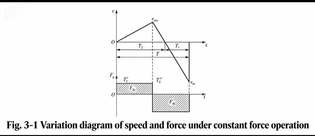
(1) Dynamische vergelijking voor de versnellingsfase van de zuiger tijdens de terugslag
Laat de aandrijfkracht tijdens de terugslag F 2g , snelheid v en versnelling een worden gedefinieerd als [+]. De equivalente aandrijfkracht die de zuiger tijdens de terugslag versnelt, is:
F 2g = p g Een ′2 = mA 2 (3.9)
waarbij: een 2= [+] — versnelling van de zuiger tijdens de terugslag;
Een ′2— effectief drukdragend oppervlak van de voorste zuigerkamer;
p g — equivalente druk van het systeem.
(2) Dynamische vergelijking voor de vertragingsfase van de zuiger tijdens de terugslag
De equivalente aandrijfkracht die de zuiger vertraagt tijdens de terugslag is:
F 3g = p g Een ′1 = mA 3 (3.10)
waarbij: een 3= [−] — vertraging (remming) van de zuiger tijdens de terugslag.
(3) Dynamische vergelijking voor de zuigerdrukstootfase
De equivalente aandrijfkracht die de zuiger versnelt tijdens de drukstootfase is:
F 1G = p g Een ′1 = mA 1 (3.11)
waarbij: een 1= [−] — versnelling van de zuiger tijdens de drukstootfase;
Een ′1— effectief drukdragend oppervlak van de achterkamer van de zuiger.
Het begrip effectief drukdragend oppervlak verschilt afhankelijk van de drie verschillende werkwijzen van de hierboven beschreven hydraulische rotsbreekhamer; dit wordt uitgebreid besproken in het hoofdstuk over dynamica.

Welkom bij HOVOO, een Chinese zegelfabriek. Productie van PU, Rubber en PTFE zegels. De zegels omvatten O-ring, pistonzegel, stangzegel, Gray ring en gaszegel.


 EN
EN
 AR
AR CS
CS DA
DA NL
NL FI
FI FR
FR DE
DE EL
EL IT
IT JA
JA KO
KO NO
NO PL
PL PT
PT RO
RO RU
RU ES
ES SV
SV TL
TL IW
IW ID
ID LV
LV SR
SR SK
SK VI
VI HU
HU MT
MT TH
TH TR
TR FA
FA MS
MS GA
GA CY
CY IS
IS KA
KA UR
UR LA
LA TA
TA MY
MY