33-99No. Mufu E Rd. Gulou District, Nanjing, China [email protected] | [email protected]
33-99No. Mufu E Rd. Gulou District, Nanjing, China [email protected] | [email protected]

A fluid is any substance that has no fixed shape. Fluids include both liquids and gases.
A liquid, like a gas, is made of molecules. But unlike a gas, the molecules in a liquid are pulled closely together — yet not so tightly that they are locked in fixed positions as in a solid. This is why a liquid flows freely and takes the shape of its container.
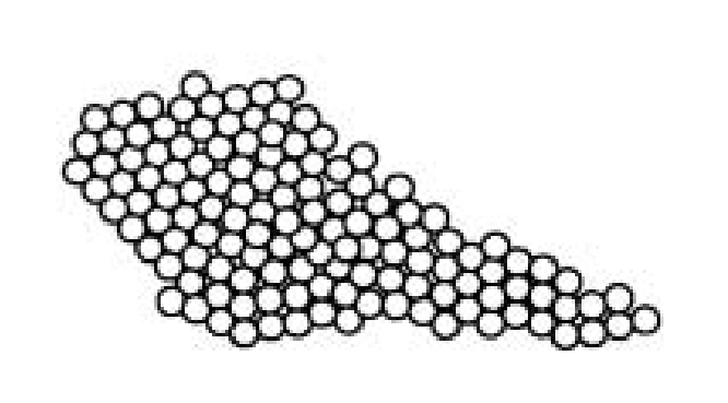
Figure 2-1 Liquid molecules (bottom) are packed closely together and in constant motion, while gas molecules (top) are far apart.
The molecules inside a liquid are always in motion — even when the liquid looks perfectly still. They are constantly sliding and gliding past each other. This molecular motion is called the internal energy of the liquid.
Because of this constant molecular sliding, a liquid flows and fills whatever container holds it. Whether there is a lot of liquid or a little, it always occupies the shape of the container. This ability is closely tied to viscosity, which is covered in later chapters.
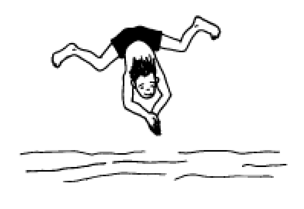
Because liquid molecules are packed closely together, liquids behave like solids in one important way: they are relatively incompressible — they cannot be squeezed into a significantly smaller volume.
This is why divers enter water feet-first or hands-first (the "knife entry") rather than belly-flopping. The water cannot move out of the way fast enough when hit with a large flat surface, and the impact is like hitting a solid. Feet or hands split the water with a small area, and the small area means much less impact force.
Because a liquid is relatively incompressible and takes the shape of any container, it has a real advantage when it comes to transmitting force.
The four methods of energy transmission (mechanical, electrical, hydraulic, pneumatic) can all transmit both static force (potential energy) and dynamic force (kinetic energy). When a static force is transmitted in a liquid, something special happens.
Unlike force acting on a solid, force applied to a confined liquid is transmitted throughout the liquid as pressure — and the pressure is equal at every point in the liquid.
If we push on a movable piston that sits on top of a container full of liquid, the force we apply generates pressure, and that pressure transmits equally in all directions through the liquid.
No matter how the pressure was created — by a piston, a hand, gravity, a spring, compressed air, or any combination — once inside a confined liquid, force converts to pressure and transmits equally throughout.
Because a liquid takes the shape of any container, pressure can be transmitted regardless of the container's shape.
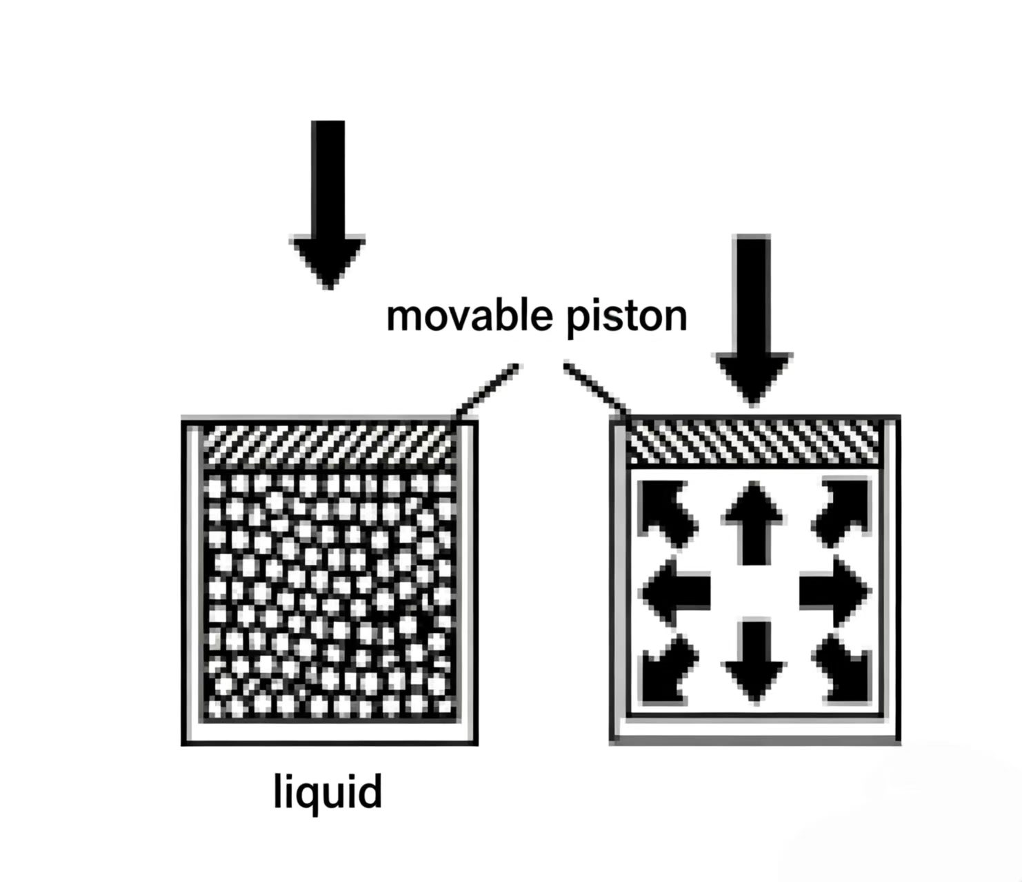
Figure 2-4 Force on the piston becomes pressure in the liquid. That pressure spreads equally in all directions — this is the key to hydraulics.
The property of a liquid to transmit pressure equally in all directions is called Pascal's Law, named after its discoverer Blaise Pascal.
The mathematical form of Pascal's Law is the same as the pressure formula introduced in Chapter 1:
Pressure (psi) = Force (lbs) / Area (in^2)
Pressure (bar) = Force (N) / [Area (m^2) x 100,000]
Pascal's Law: pressure applied to a confined fluid is transmitted undiminished in all directions throughout the fluid and acts with equal force on all equal areas.
A pressure gauge measures the pressure acting on a liquid in the system. The two most common types in hydraulic systems are the Bourdon tube gauge and the piston-type gauge.
A Bourdon tube gauge consists of a dial face and a pointer. The pointer connects to a curved, flexible metal tube called the Bourdon tube. System pressure enters the tube through the inlet. The scale is usually marked in psi, bar, or Pa.

As system pressure rises, the difference in area between the inside and outside of the curved tube tends to straighten it. This straightening motion drives the pointer across the dial to indicate the pressure. Bourdon tube gauges are precision instruments with accuracy of 0.1% to 3.0% of full scale; they are used in lab testing or wherever pressure measurement accuracy is critical.
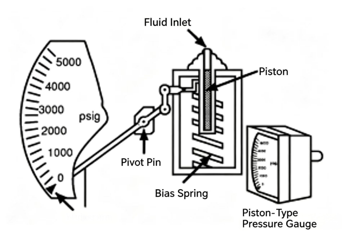
A piston-type gauge consists of a piston, a balance spring, a pointer, and a scale. System pressure acts on the piston face, pushing it against the spring. The piston movement drives the pointer across the dial. The scale is calibrated in psi (bar). Piston gauges are durable and economical — a common choice for everyday system monitoring.

Figure 2-6 Piston-type gauge: system pressure pushes the piston against a spring. The piston displacement moves the pointer.
Transmitting pressure through a sealed liquid is useful only if the pressure can be converted back to mechanical force somewhere. That is the job of the actuator (执行元件) — it receives hydraulic pressure and converts it into mechanical force.
A hydraulic cylinder is one type of actuator.
A hydraulic cylinder receives hydraulic pressure and converts it into straight-line (linear) mechanical force. Through suitable mechanical linkages it can also be converted to rotational motion.
A cylinder's basic parts are: the barrel (tube), end caps, piston, piston rod, and inlet/outlet ports. Each end has one end cap. The piston can slide inside the barrel. The rod connects to the piston. The inlet and outlet ports at each end of the barrel let working oil flow in and out.
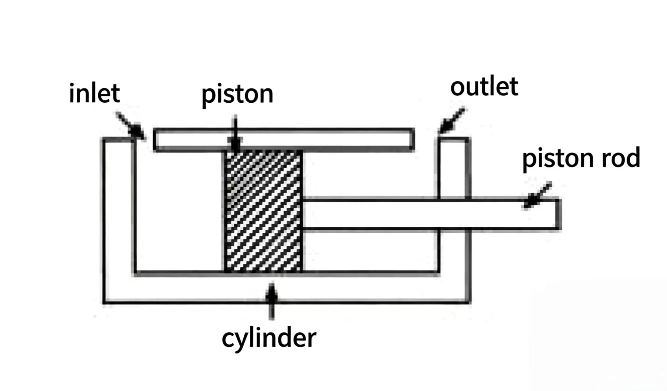
Figure 2-8 Hydraulic cylinder cross-section. Oil enters one port, pushes the piston, and the rod extends. Oil leaving the other port returns to tank.
When the cylinder inlet port is connected to the system, the cylinder becomes part of the system. Pressure from point A transmits through the system to the piston inside the cylinder. That pressure acting on the piston area produces mechanical force at point B — at the rod end.
When pressure is transmitted through a sealed liquid, some moving part generates the pressure. In all the examples so far, the moving part is a piston. Dividing force by the piston area gives the pressure in the system (P = F/A).
Hydraulics can amplify (multiply) mechanical force. The multiplication factor depends on the area of the hydraulic cylinder piston (in² or cm²). Because pressure is transmitted equally through a sealed liquid, if the output cylinder piston is larger than the input piston, the output force is greater than the input force.
Example: A 5,000 lbs (22,200 N) force acts on a piston with area 10 in² (64.52 cm²), producing a pressure of:
P = F / A = 5,000 lbs / 10 in^2 = 500 psi (34.5 bar)
That same 500 psi acts on a 15 in² (96.78 cm²) output piston:
F_out = P x A_out = 500 psi x 15 in^2 = 7,500 lbs (33,360 N)
Force multiplication formula: F_out = P x A_out where P = F_in / A_in
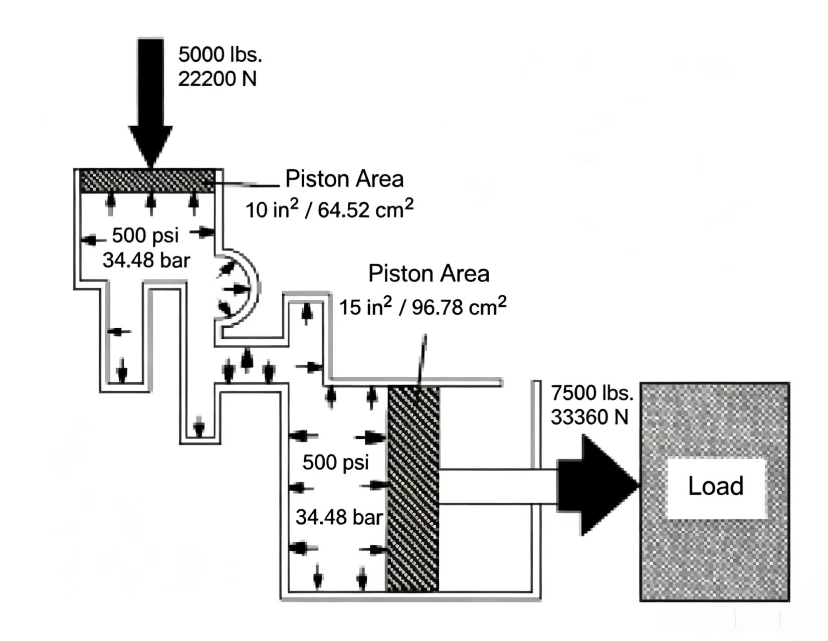
Figure 2-9 Mechanical force multiplication. The same pressure acts on both pistons, but the larger piston produces more force. F = P x A.
A pressure intensifier (also called a booster) can amplify hydraulic pressure. It uses two pistons connected by one rod inside a single housing with inlet, outlet, and drain ports. The large piston senses the system pressure; the force it generates is applied to the small piston, which produces a higher output pressure because the area is smaller.
The large piston senses system pressure and transmits that force through the rod to the small piston. Because the small piston has a smaller area, the output pressure at the small piston end is higher — pressure is intensified.
Example: A 5,000 lbs (22,200 N) force acts on the large piston (area: 15 in² / 96.78 cm²). Pressure = 333 psi (22.9 bar). That force is transferred to the small piston (area: 0.76 cm²). Output pressure = 5,000 lbs / 0.76 cm² x (1/10,000) = 2,000 psi (137.9 bar). Output force = 30,000 lbs (133,200 N).
A common use for pressure intensifiers is in clamping fixtures.

Figure 2-11 Pressure intensifier. The large piston transfers its force to the small piston, which has a much smaller area — producing much higher pressure at the output.
The purpose of using hydraulics (or any other energy transmission method) in a machine is to do useful work. For a cylinder to do work, it must apply force to the load and move it through a distance — so the system needs a component that can use energy to provide a continuous flow of liquid.
Everything we have looked at so far that creates pressure in a sealed liquid uses pistons and cylinders. The piston applies force; the cylinder seals the liquid. This kind of device is called an accumulator.
An accumulator can store the potential energy of a liquid under pressure. That stored potential energy can be converted to working energy (flow and pressure).
Example: A 500 psi (34.5 bar) accumulator provides pressure to push a load. Of the 500 psi stored, 400 psi (27.6 bar) is used to overcome the load resistance, and the remaining pressure converts to flow to move the load.
Accumulators do have a limitation: if the load is very large, there may not be enough pressure to overcome it, so no work can be done. Also, once the stored liquid is fully released, there is no more flow.
To apply enough pressure to overcome a load and keep supplying flow continuously, a different device is needed — the positive-displacement hydraulic pump.

Figure 2-12 Accumulator operation. Stored pressure can push a load, but once the fluid is exhausted, flow stops — the accumulator cannot sustain continuous work alone.
A positive-displacement pump produces a continuous flow of liquid by repeated reciprocating or rotary internal motion. It provides both kinetic energy (flow) and pressure energy — the working energy needed to do continuous hydraulic work.
A reciprocating piston pump has a piston connected to a prime mover (engine or electric motor) through a crank or cam. The inlet and outlet each have a ball-type check valve. When the piston is pulled out, the internal volume expands, the inlet ball opens and liquid flows in. When the piston is pushed in, volume shrinks, pressure builds, the inlet ball closes, and the outlet ball opens — pushing liquid into the system. Continuous back-and-forth motion produces a pulsating flow; pressure can be whatever the system requires.
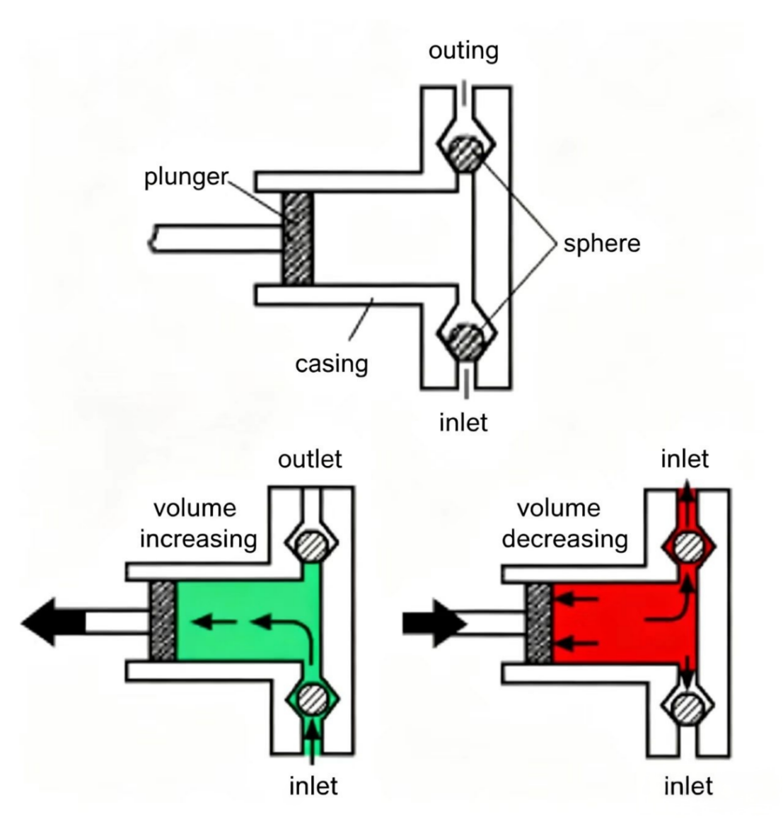
Figure 2-13 Reciprocating piston pump. The piston moves in and out, drawing oil in through the inlet check and pushing it out through the outlet check.
The most common pump in industrial hydraulic systems is the rotary positive-displacement pump. It produces a relatively smooth, pressurized flow and is easy to drive with an electric motor or engine. Each revolution of the rotating element displaces a fixed volume of liquid.
A rotary pump has a housing and a rotating assembly. The housing has an inlet and an outlet. The rotating assembly generates the flow and pressure. The example shown has a rotor and vanes that can slide freely in and out of the rotor slots.

The rotating assembly is mounted eccentrically (off-center) inside the housing and connected to the prime mover by the drive shaft — the rotor spins. As the rotor turns, centrifugal force pushes the vanes outward against the housing wall, forming sealed chambers. On the inlet side the chamber volume grows, liquid is drawn in. On the outlet side the chamber shrinks, pressure builds, and liquid is pushed out of the system. The pump only produces pressure equal to the minimum resistance in the system — nothing more.
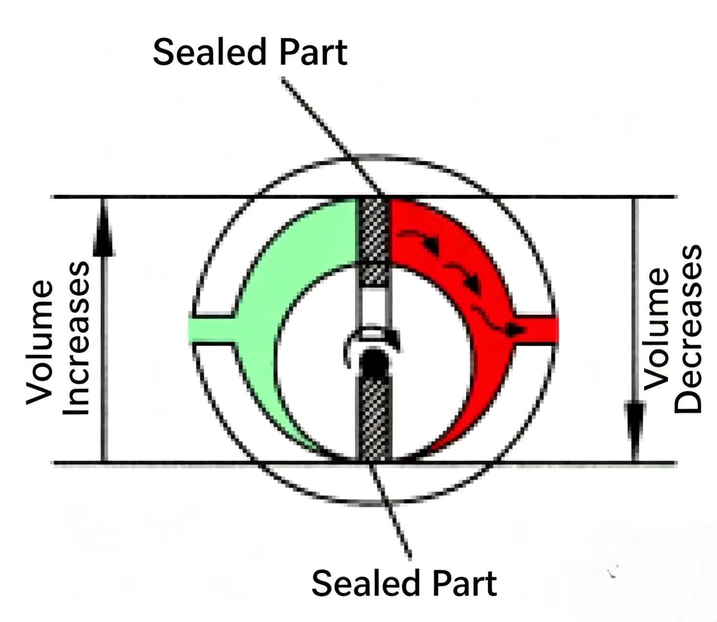
Figure 2-15 Rotary vane pump. Vanes sealing against the housing wall create chambers that expand (inlet) and contract (outlet) as the rotor spins.
In a hydraulic system, pressure and resistance are directly related. The pump pushes liquid into the system; the level of pressure is determined by the level of resistance. High resistance → high pressure; low resistance → low pressure. The resistance to fluid flow determines how much pressure is produced.
A pump faces two types of resistance: load resistance and flow resistance. If we ignore flow resistance, the only resistance is the load. If 200 psi (13.8 bar) is needed to overcome the load resistance, the pump produces 200 psi and drives hydraulic working energy into the actuator, which then moves the load.
Flow resistance is always present. It forces the pump to draw more energy from the prime mover and produce higher pressure to overcome it.

Figure 2-16 Resistance and pressure. The pump pressure rises to overcome whatever total resistance it faces — load resistance plus flow (friction) resistance.
The extra energy the pump puts into the liquid to overcome flow resistance is not converted to useful hydraulic working energy at the actuator — it is consumed by the flow friction. This "consumed" energy is not lost in the conservation sense; it is converted to heat, which raises the fluid temperature. This heat is the system's inefficiency.
In a dynamic (flowing) hydraulic system, liquid moves through pipes at a certain velocity (speed). Velocity is measured in ft/s (feet per second) or m/s.
The volume of liquid passing a point per unit of time is called the flow rate. In hydraulic systems the unit is usually gpm (US gallons per minute) or Lpm (liters per minute).
Velocity and flow rate are related: to fill a 5-gal (18.95 L) container in one minute through a large pipe, the liquid moves at 10 ft/s (3.04 m/s). Through a pipe half as large, the liquid must move at 20 ft/s (6.10 m/s) to deliver the same 5 gpm. Flow rate is the same; velocity is different.
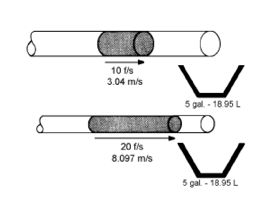
Figure 2-17 Same flow rate, different velocity. In a smaller pipe, the fluid must move faster to pass the same volume per minute.
Liquid flowing through hydraulic pipes generates heat due to friction — the faster it flows, the more heat is produced. In industrial applications, the recommended fluid velocity inside the lines between the pump and actuator is 15 ft/s (4.572 m/s).
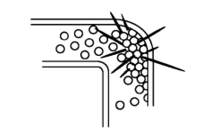
Liquid flowing in a straight pipe that reaches a bend has to change direction suddenly. Fluid molecules collide with each other and with the pipe wall — this also generates heat. Depending on pipe size, a single 90° elbow can generate as much heat as several feet of straight pipe.
A pressure differential is the difference in pressure between any two points in a system. A pressure differential tells you two things:
Example: Pressure gauge 1 reads 200 psi (13.79 bar); pressure gauge 2 reads 180 psi (12.41 bar). The differential = 20 psi (1.38 bar). This means:

Figure 2-19 Pressure differential. The 20 psi drop across this pipe section shows flow is present and quantifies the hydraulic energy lost to friction heat.
Converting hydraulic energy to heat means the system is wasting energy. To improve efficiency, designers must choose the right oil viscosity, size pipes correctly, and minimize the number of bends and fittings. All of these reduce flow resistance and thus reduce the energy lost as heat.

Figure 2-20 Heat generation in a real circuit. Every pipe, fitting, bend, and valve contributes to pressure drop and energy loss.
KEY FORMULAS - CHAPTER 2
|
Concept |
Formula |
Units / Notes |
|
Pascal's Law / Pressure |
P = F / A |
psi = lbs/in^2 | bar = N/(m^2 x 100,000) |
|
Force from pressure |
F = P x A |
lbs = psi x in^2 |
|
Force multiplication |
F_out = (A_out / A_in) x F_in |
Ratio of piston areas determines gain |
|
Pressure intensification |
P_out = (A_in / A_out) x P_in |
Smaller output area = higher output pressure |

Welcome to HOVOO, a Chinese seal factory. Production of PU, Rubber and PTFE seals. The seals include O-ring, piston seal, rod seal, Gray ring and gas seal.


 EN
EN
 AR
AR CS
CS DA
DA NL
NL FI
FI FR
FR DE
DE EL
EL IT
IT JA
JA KO
KO NO
NO PL
PL PT
PT RO
RO RU
RU ES
ES SV
SV TL
TL IW
IW ID
ID LV
LV SR
SR SK
SK VI
VI HU
HU MT
MT TH
TH TR
TR FA
FA MS
MS GA
GA CY
CY IS
IS KA
KA UR
UR LA
LA TA
TA MY
MY