33-99No. Mufu E Rd. Gulou District, Nanjing, China [email protected] | [email protected]
33-99No. Mufu E Rd. Gulou District, Nanjing, China [email protected] | [email protected]

In addition to transmitting energy, petroleum-based oil has one other critical function: lubrication. Both functions — energy transmission and lubrication — are strongly influenced by viscosity. This makes viscosity the single most important property of hydraulic oil.
Lubrication is the process of reducing friction between two surfaces that are in contact and moving relative to each other.
Lubrication is a critical function of hydraulic oil. Without lubrication, friction between moving parts causes excessive wear and generates heat.
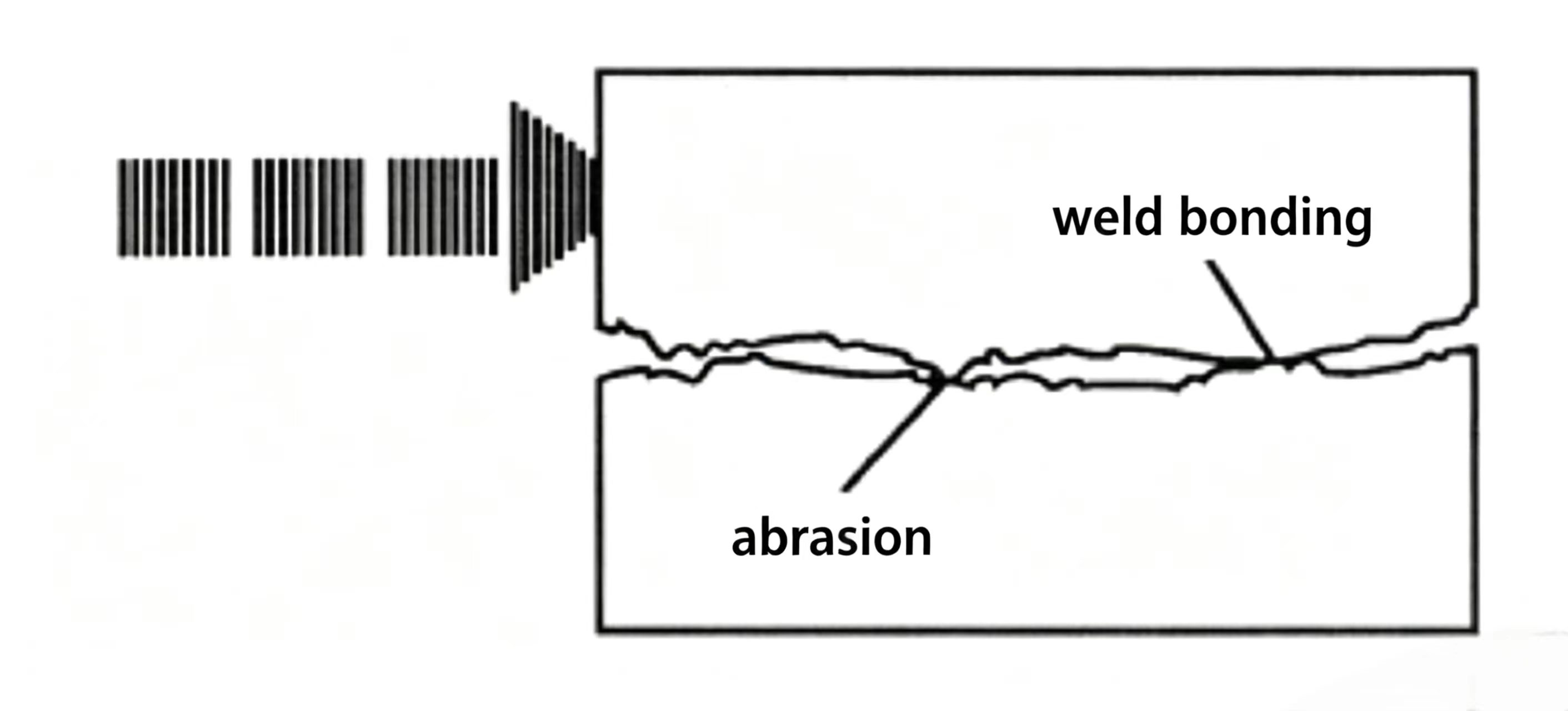
Friction is a force that opposes motion. Even surfaces that look smooth are microscopically rough. When two surfaces rub together, the microscopic high points contact, deform, weld together, and tear apart — this tearing is friction. The rougher the surface, the greater the sliding force needed and the more friction is generated.
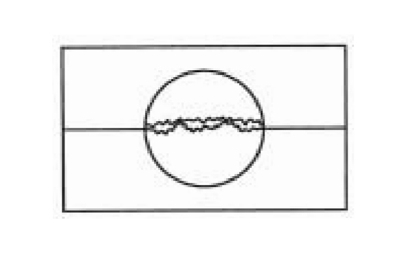
Figure 3-1 Friction occurs when microscopic high-spots on two surfaces contact, weld briefly, and tear apart as the surfaces slide.
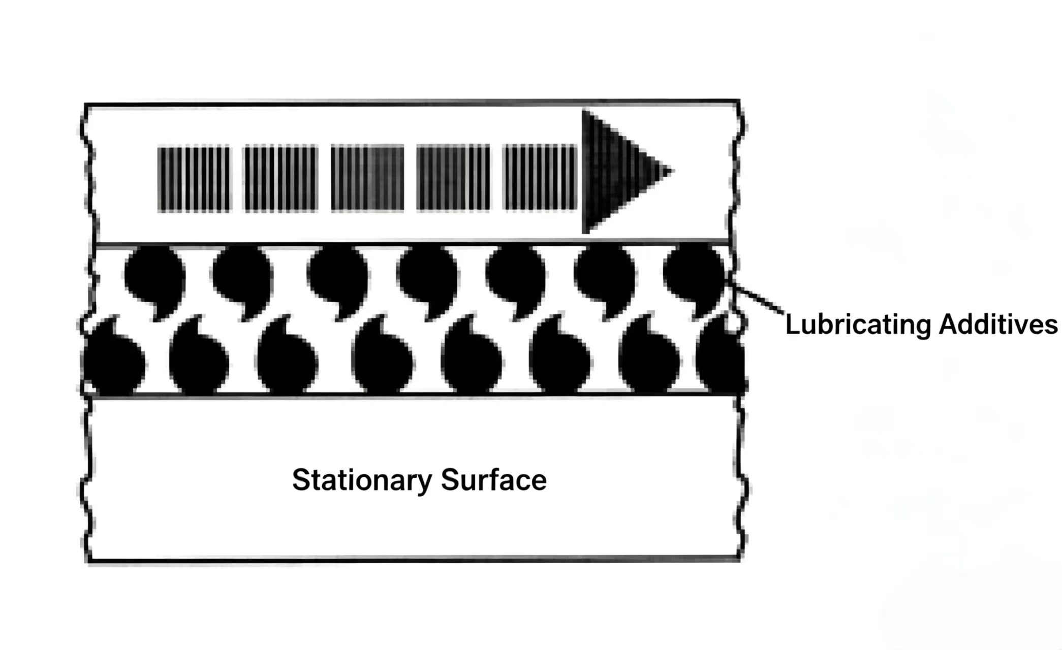
If there is an oil film between two metal surfaces, the direct metal-to-metal contact is eliminated. The surfaces slide on the oil film instead of on each other, dramatically reducing friction.
Any liquid can form an oil film, but some liquids are better than others. Water, for example, was used as the first hydraulic fluid, but its film is weak and easily broken. Petroleum-based hydraulic oil forms a much stronger, more resistant film.
Lubricity is the ability of a liquid to form a film that is hard to break. It depends on:
Petroleum hydraulic oil has excellent lubricity. Pour it on a steel plate and you will see a large, thick oil film coat the surface and stay there. Pour water on the same plate, and a thin film forms but breaks easily. Pour mercury, and it beads up into spheres — mercury has almost no adhesion to steel, so its lubricity is very poor.
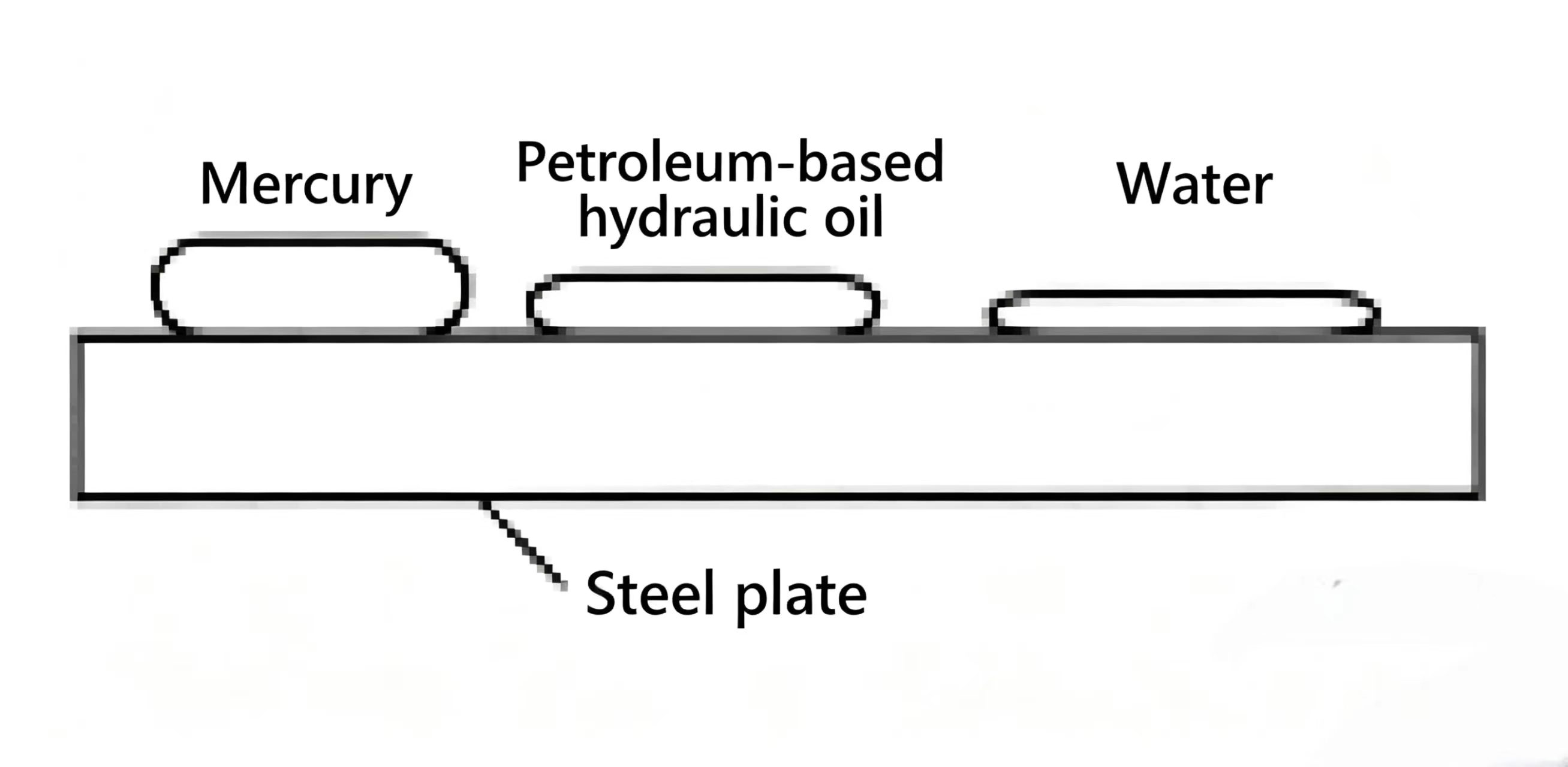
Figure 3-2 Lubricity comparison. Good lubricity requires both a naturally thick film and strong adhesion to the metal surface. Oil wins on both counts.
The right hydraulic oil viscosity must balance two needs: the oil must be thick enough to form a good film, but still fluid enough to flow freely. This balance is explored next.
Oil has two important functions in a hydraulic system:
Both of these functions — and their ultimate effect on the system — are strongly influenced by viscosity. Let us first define viscosity, then examine its effect on heat generation, lubrication, dynamic lubrication, clearance flow, and more.
Like all liquids, petroleum hydraulic oil is made of molecules that attract each other. The molecular attraction in a liquid is much stronger than in a gas, but weaker than in a solid (where molecules are locked in fixed positions). Because liquid molecules can slide past each other, a liquid can flow continuously.

Viscosity is a property that resists the flow of liquid molecules past one another — it is a form of internal friction. A high-viscosity liquid (like honey or molasses) flows slowly and with great resistance. A low-viscosity liquid (like water or cooking oil) flows easily.
As mentioned above, liquid consists of molecules in constant motion that attract each other. When molecules move slowly, the attraction between them is stronger, and the resistance to flow is greater — viscosity is high. When molecules move fast (when heated), the attraction weakens and viscosity drops.
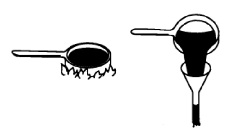
Cold molasses from the refrigerator has very high viscosity — it pours slowly and with effort. Heat it on the stove and the molecules speed up, attraction weakens, viscosity drops, and it flows through a funnel with ease.
One way to measure oil viscosity is with Saybolt Universal Seconds (SUS, also called SSU). The SI unit is centistokes (cSt). SUS was named after George Saybolt, who proposed the Saybolt viscometer to the US Bureau of Standards in 1919.
Method: Pour the liquid into a container and heat it to the test temperature. Pull out the bottom plug and start a stopwatch at the same instant. Stop the watch when exactly 60 mL of liquid has drained into a flask. The elapsed time in seconds is the SUS viscosity at that temperature.
Example: If oil heated to 100°F (37.7°C) takes 143 seconds to drain, its viscosity is 143 SUS @ 100°F (37.7°C). If the same oil heated to 130°F (54.4°C) takes 82 seconds: viscosity = 82 SUS (17.7 cSt) @ 130°F (54.4°C). Viscosity always depends on temperature, so you must always state both the value and the temperature. "150 SUS (32 cSt)" without a temperature is shorthand for 150 SUS (32 cSt) @ 100°F (37.7°C).
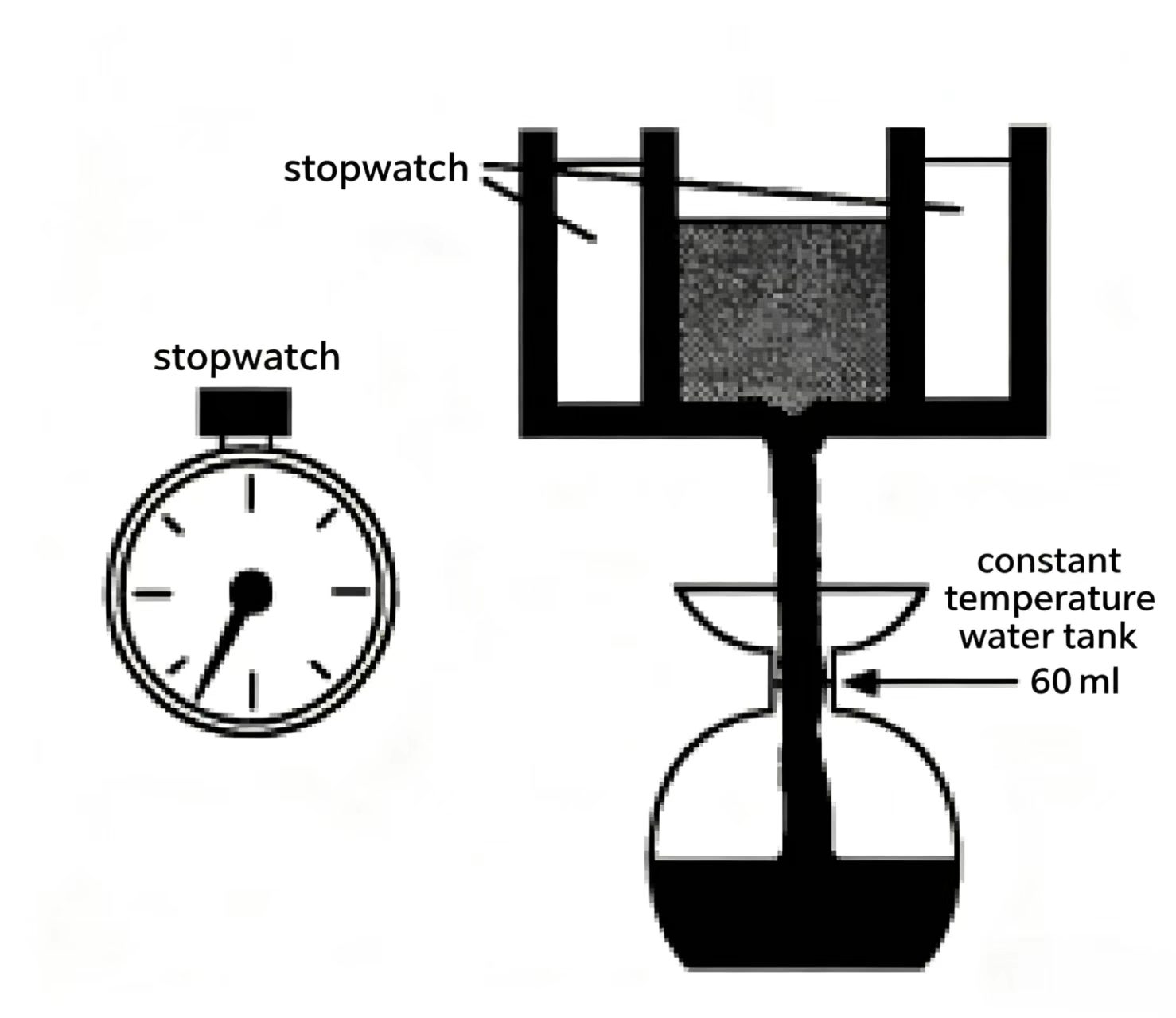
Figure 3-5 Saybolt viscometer. Oil is heated to a set temperature, then timed as exactly 60 mL drains into the flask. The time in seconds = SUS viscosity.
Viscosity also changes with system pressure. As pressure rises, viscosity rises with it (shown by the curve in the figure). A pressure increase from 0 to 3,000 psi (207 bar) can raise the viscosity of typical industrial hydraulic oil by about 40%.
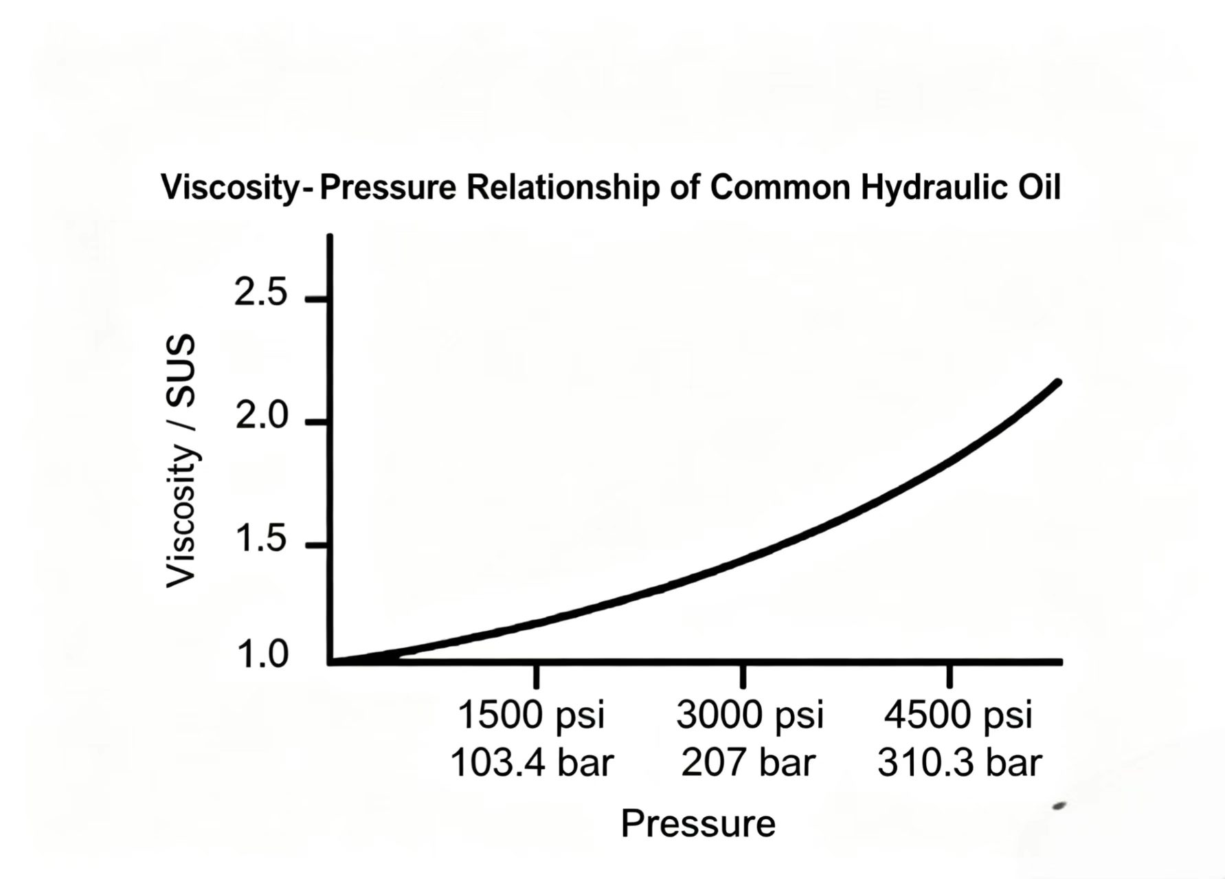
Figure 3-6 Viscosity rises with pressure. At 3,000 psi (207 bar), viscosity can be 40% higher than at atmospheric pressure.
Viscosity directly affects heat generation. High-viscosity oil (e.g., 500 SUS / 107.9 cSt) creates more internal flow resistance than low-viscosity oil (e.g., 150 SUS / 32 cSt), generating more heat in the system.
In most hydraulic systems, the working viscosity range is 150–250 SUS (32–53.9 cSt) @ 100°F (37.7°C).
Viscosity is a resistance to flow, so it might seem undesirable. But it has a major effect on lubrication — it is extremely important for forming a good oil film. Higher viscosity means a thicker, stronger film. But the oil also needs to flow freely, so the right viscosity must balance both needs.

Figure 3-7 Oil film thickness varies with viscosity. High viscosity gives a thicker film but increases flow resistance. Low viscosity flows easily but the thin film may break under load.
The ability to form a firm oil film is an important property of petroleum hydraulic oil. We call this ability lubricity. It might seem that high-speed moving parts would be hard to lubricate because the speed would wipe the film away — but in fact, the viscosity of the liquid normally prevents this.
When a stationary metal block sits on an oiled metal surface and a force pushes it, the leading edge of the block is lifted slightly. The oil resists being squeezed out (due to viscosity), and an oil wedge forms under the block. The wedge supports the block as it moves — like a boat on water. As long as the pressure on the moving block stays within a certain range, the oil wedge prevents the surfaces from making direct metal contact. This is dynamic (hydrodynamic) lubrication.
Low-viscosity liquids like water, under low-speed and high-load conditions, are easily squeezed out — the wedge cannot fully form, and the film breaks easily.
When system components are in motion, the hydrodynamic process provides good lubrication. But at start-up, or when the pressure driving the components is excessive, the ability of the oil to form a firm film (lubricity) becomes critically important.

Figure 3-8 Hydrodynamic lubrication. As the block moves, an oil wedge forms that supports the load and keeps the surfaces from making metal-to-metal contact.
Viscosity also affects how well oil seals the close-fitting clearances between moving parts. Many hydraulic components (pumps, motors, valves) rely on metal-to-metal sealing — there are no rubber seals between, say, a piston and its bore in a piston pump. There is only a thin film of oil in the clearance gap.
The clearances between these parts act like fixed orifices — they continuously throttle a small leakage flow. This leakage both lubricates and seals. Too little leakage means inadequate lubrication; too much means the system loses flow, efficiency drops, and unnecessary heat is generated.
For best sealing, clearances should be as small as possible — but not so small that the oil cannot lubricate, and not so large that excessive leakage occurs. The optimal gap balances sealing and lubrication.
When the oil viscosity is too low (oil too thin), leakage through the clearances becomes excessive. This reduces the flow reaching the actuators and generates unnecessary heat. When viscosity is too high, the film still forms but flow resistance rises and system efficiency drops.
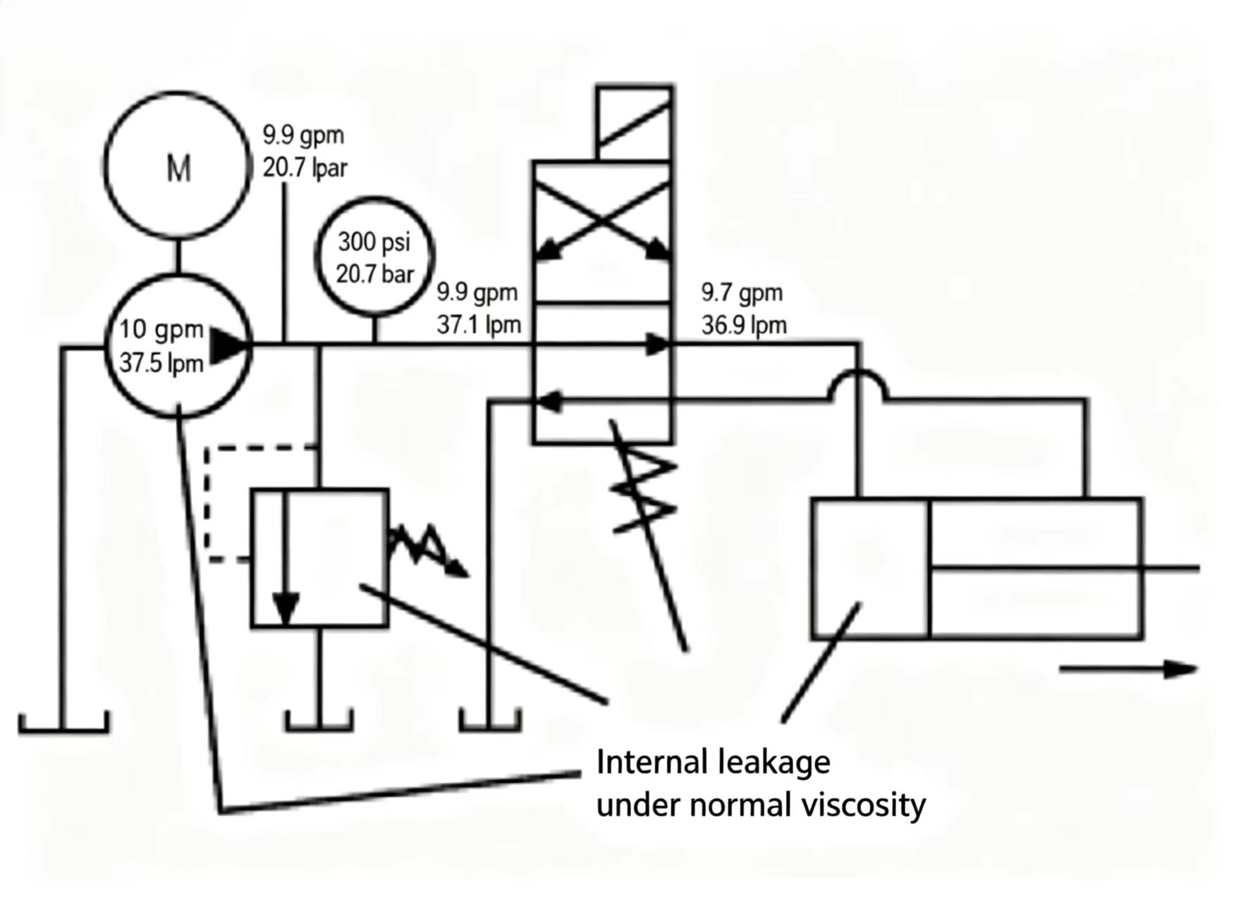
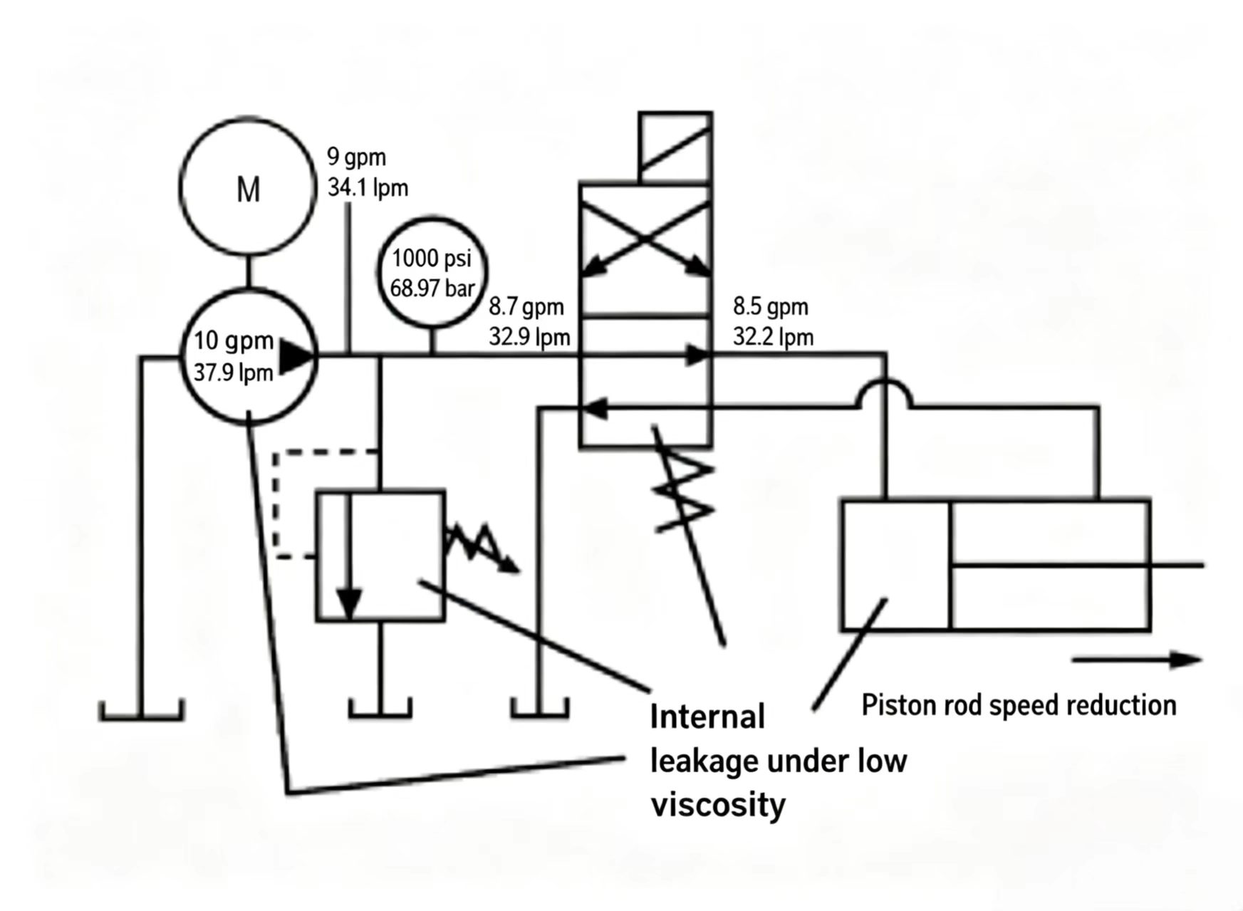
Figure 3-9 Effect of low viscosity on internal leakage. With thin oil, leakage through the metal-to-metal clearances increases, reducing the flow that reaches the actuator.
Hydraulic oil viscosity is an important parameter in a hydraulic system. But viscosity changes with temperature, so if the system cannot maintain a constant operating temperature, the oil viscosity must remain relatively stable across the operating temperature range.
The Viscosity Index (VI) describes how much viscosity changes with temperature. The relationship uses the ASTM (American Society for Testing and Materials) standard viscosity-temperature chart: when the oil's viscosity at two different temperatures is plotted on this chart, the result is a straight line. The viscosity at any other temperature can then be read from that line (this method is valid for base oil without chemical additives; additives can affect the natural viscosity/temperature relationship).
If two oil curves are plotted on the same chart, the more horizontal line is the higher-VI oil. For example:
Oil A has a flatter line — its viscosity changes less with temperature — so Oil A has a higher Viscosity Index.
When the VI concept was first introduced, the scale ran from 0 (worst, most sensitive to temperature) to 100 (best, least sensitive). Modern refining methods can produce oils with VI over 100. In modern hydraulic systems, VI ≥ 90 is typically required, though for systems running at a relatively constant temperature, VI matters less.

Figure 3-10 ASTM viscosity-temperature chart. The more horizontal the line, the higher the Viscosity Index — the oil is less sensitive to temperature change.
Petroleum hydraulic oil is a good lubricant for hydraulic systems, but it has a viscosity range within which it works best. If oil viscosity is too low, the oil film is too thin (like water), and components suffer wear. If viscosity is too high, oil cannot flow into bearings fast enough and components starve.
Rotary components — hydraulic pumps and motors — especially need good bearing lubrication. Pump manufacturers specify the viscosity range for their products. If those components are properly lubricated, all other system components are adequately lubricated too.
Once the required viscosity range is known, the system operating temperature range determines which specific hydraulic oil to choose. For example, if a system requires viscosity between 70–250 SUS (15–54 cSt) and the operating temperature is 80–140°F (26.7–60°C), choose Oil Y. If the temperature range is 110–170°F (43.3–76.7°C), choose Oil Z.
Even in industrial environments, temperature can get very low. To ensure the pump can draw oil normally on startup, pump manufacturers specify the maximum allowable startup viscosity: typically 1,000 SUS (216 cSt) for piston pumps, and 7,500 SUS (1,618 cSt) for vane and gear pumps.
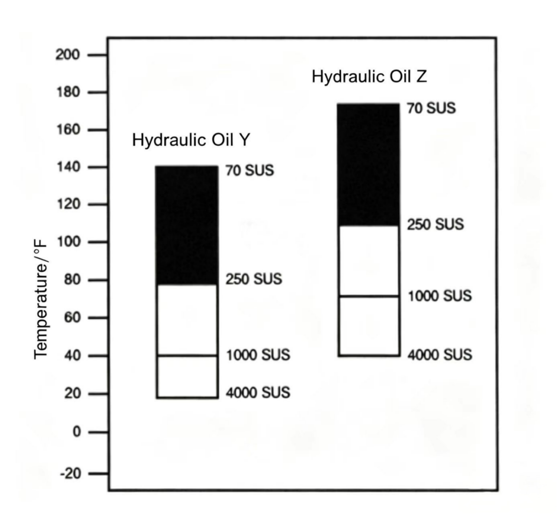
Figure 3-11 Selecting oil grade by operating temperature. The shaded band shows the usable viscosity range. Choose the oil whose band covers your operating temperature range.
The ASTM viscosity chart does not show the pour point. At very low temperatures, petroleum oil stops flowing altogether — waxy paraffin crystals precipitate out of the oil and block flow. The pour point is the lowest temperature at which a hydraulic oil can still flow, measured under ASTM lab conditions.
In a real system, if the maximum startup viscosity requirement is met, the pour point usually does not need to be checked separately. However, if the system may operate at extreme low temperatures, the oil pour point must be at least 20°F below the minimum expected operating temperature.
Pour point data for any given oil can be found on its product data sheet.
As a hydraulic system runs day after day, petroleum oil is subjected to demanding conditions. Several problems can develop that affect both the oil and the system: high-pressure lubrication, oil oxidation, water contamination, air ingestion, and solid particle contamination. Chemical additives in the oil address many of these issues.
Important: Chemical additives cannot fully solve every oil problem, and no oil can contain every additive. A "super oil" that does everything does not exist. Many additives are incompatible with each other — mixing oils with different additive packages from different suppliers can produce harmful reactions.
A good-quality petroleum hydraulic oil is not always a good lubricant at high pressure. When pressure rises, the oil wedge between moving parts is more easily broken, and the adhesive film (lubricity) becomes critical. Chemical additives can improve high-pressure lubrication or boundary lubrication.

There are three types of anti-wear additive:
The three types cannot all be used in the same oil — they serve different purposes. Oiliness/WR additives are for lower-pressure systems (below 1,000 psi / 68.97 bar). EP additives are mainly for systems above 3,000 psi (207 bar) or for gear and machine-tool lubricants. AW additives serve the middle range (1,000–3,000 psi / 68.97–207 bar).
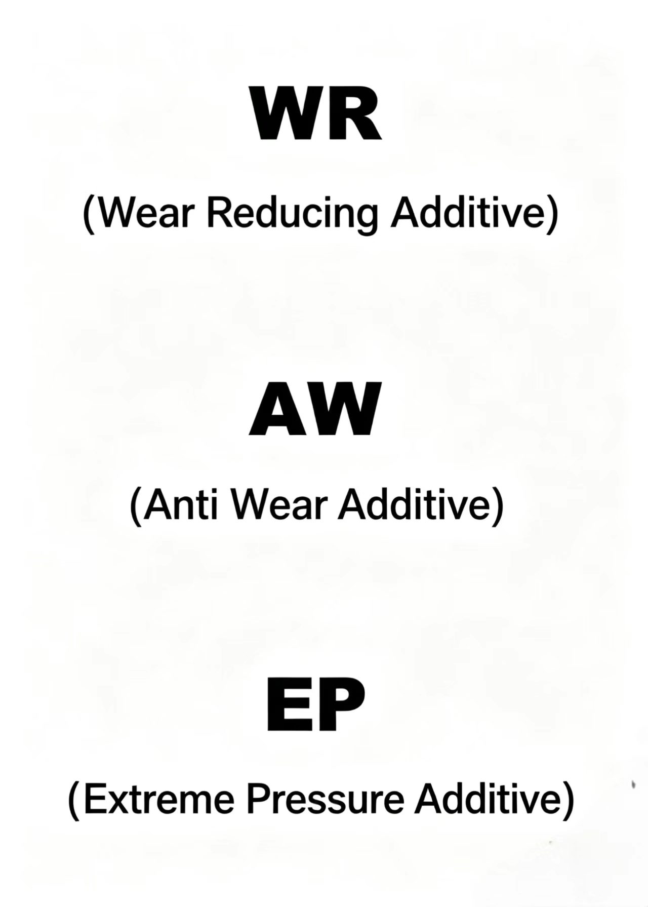
To check whether an oil has anti-wear additives, look for the oil name or consult the supplier's data sheet. Example: "Hamony 48 AW" (Gulf Oil Co.) — "AW" indicates anti-wear; "Sunvis 816 WR" (Sun Oil Co.) — "WR" indicates wear-reducing.
Many refined oil producers do not label the anti-wear content in the product name; for specific oils, always consult the data sheet. If a system has excessive wear problems and the oil lacks anti-wear additives, switching to an AW oil may help — but first confirm the wear is not caused by oil contamination.
Oxidation is the chemical reaction of a material with oxygen — a common process. When you bite an apple and the flesh turns brown, that is oxidation. A car fender scratched and exposed to the air reacts with oxygen and rusts. Much of the world, including oil, oxidizes in this way.
Oil oxidation in a hydraulic system occurs mainly in two places: the reservoir and the pump outlet. Both involve oil-oxygen contact, but the oxidation process is different in each.
In the reservoir, the oil's free surface reacts with oxygen in the air. The products of this reaction include weak acids and soap-like materials. The acids corrode component surfaces and produce dark stain spots. The soaps coat component surfaces and block the small orifices in pressure-sensing ports and lubrication passages.
Heat accelerates oil oxidation. Every 18–20°F (10–11°C) above the average reservoir temperature (130°F / 54.4°C) approximately doubles the rate of oxidation. Iron, copper particles, and water drops in the oil also speed up oxidation.
The second place oil oxidizes is at the pump outlet. If the suction line leaks air or the return oil disturbs the reservoir and causes the pump inlet to take in air bubbles, those air bubbles reach the high-pressure pump outlet and suddenly implode (collapse violently) under high pressure. This process generates extreme local heat. Calculations show that when a bubble is compressed from near zero to 3,000 psi (207 bar), the temperature can reach 2,100°F (1,149°C). At this temperature the oil ignites, producing resin-like deposits and an acrid burning smell.
If oxidation products form at the pump outlet, the resin dissolves into the oil. When the resin contacts hot surfaces (pump rotor, relief valve spool, etc.), it precipitates out of the oil as varnish deposits on those surfaces, causing moving parts to stick and jam.
The resin in the oil also combines with dust and particles to form sludge, which blocks small orifices in valves and filters, and prevents heat from escaping through reservoir walls. Bubble implosion at the pump outlet is a major cause of rapid oil oxidation.

Figure 3-14 Air bubble implosion at the pump outlet. When bubbles are compressed from low to high pressure, local temperatures can exceed 2,000°F — enough to ignite the oil and form varnish deposits.
Compare a sample of oil from the system (possibly oxidized) with a fresh oil sample from the drum, at the same temperature. Fresh oil feels distinctly sticky when rubbed between thumb and finger, and stays on the fingers. Oxidized oil feels watery — it runs off like water, with poor tackiness and adhesion.
Oil oxidized by bubble implosion also has a sharp, acrid smell. If the sample shows signs of oxidation, send it to a lab for analysis. If it cannot be reconditioned, flush the system and refill with fresh oil.

Any hydraulic oil contains some moisture. In small amounts, water breaks into tiny droplets and is carried by the oil. Water and oil do not mix (except for water-soluble oils); in large amounts, water settles to the bottom of the reservoir.
If the oil already contains oxidation-produced acids and resins, they will accelerate water retention.
Comparing the suspect sample with a fresh oil sample is the basic check. Place fresh oil in a glass flask and hold it up to light — it is clear with slight bubbles. If a sample contains 0.5% water, it looks cloudy or foggy. At 1% water, it looks milky.
Another method: heat the milky/foggy sample — if it clears up after a while, water was likely present. If the oil contains a large amount of water, most of it will eventually settle out; centrifugal separation can speed this up if time matters.
If the oil has only a small amount of water (< 0.5%), and the system requirements are not extremely tight, it may not need to be replaced immediately. Water in oil accelerates oxidation and reduces lubricity; the water itself eventually evaporates, but the oxidation products it caused remain and continue to do damage. If the oil is borderline, send it to a lab.
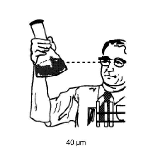
Figure 3-16 Visual water check. The amount of water in oil can be estimated by how cloudy the sample appears when held up to light.
From a hydraulic system perspective, corrosion is the chemical attack on component surfaces caused by acids formed during oil oxidation. Rust is the oxidation of iron-based surfaces caused by water in the oil.
Corrosion dissolves metal and washes it away — reducing the size and weight of precision parts. Rust adds material to iron surfaces — increasing their size and weight. When precision components change in size, their efficiency and performance are affected. Neither corrosion nor rust is acceptable in a hydraulic system.
Even very small amounts of water in the oil can cause rust on iron component surfaces. Under natural conditions, oil alone does not provide enough corrosion protection, and it is practically impossible to keep all water out of a hydraulic system — so most hydraulic oils contain rust inhibitors, which form a chemical protective film on metal surfaces.
The air-oil interaction in the reservoir also produces oxidation products that eventually attack metal surfaces and accelerate further oil oxidation. So oxidation inhibitors are also added — these chemicals interrupt the oxidation chain reaction.
High-temperature oxidation from bubble implosion at the pump outlet cannot be prevented with chemistry alone; it can only be controlled by eliminating air from the pump inlet flow. R&O additives are the basic additive package in most industrial hydraulic oils. Oils with these additives are sometimes called "R&O oils." Premium-grade transparent (clear) R&O oils are the highest quality; lower grades of turbine oils may still be suitable for many hydraulic applications and are labeled "below turbine quality R&O."

Oil returning to the reservoir should release any entrained air from the system. In some systems, the suction-side air leaks are severe, and when return oil splashes into the reservoir, it generates foam — which eventually causes entrained air to be drawn back into the pump, causing system instability, accelerating oxidation, generating noise, and potentially causing oil to overflow the reservoir, creating an environmental hazard.
The best solution is to fix the leaks and redesign the return circuit, for example: using a reservoir baffle, using a larger return line to reduce the velocity of oil entering the reservoir. For economic, practical, or training reasons, chemical additives may be used instead.
Anti-foam additives prevent oil foaming. Some work by combining small bubbles into large ones that rise to the surface and burst. Another type works by interfering with air release to reduce foam but increases the number of tiny bubbles in the system. When choosing an anti-foam additive, make sure to select the type that allows air to escape — not the type that traps more air.
Check oil foam by taking a sample from the reservoir. Visual inspection tells you quickly whether the oil contains air. Samples should be taken as close to the pump inlet as possible so the sample represents the oil actually entering the system.
Other signs of air in the system: high-pitched, irregular noise from the pump; the pump may periodically make a loud hammering sound, as if someone is firing a gun inside. Erratic cylinder movement and unstable pressure gauge readings are also signs of air.
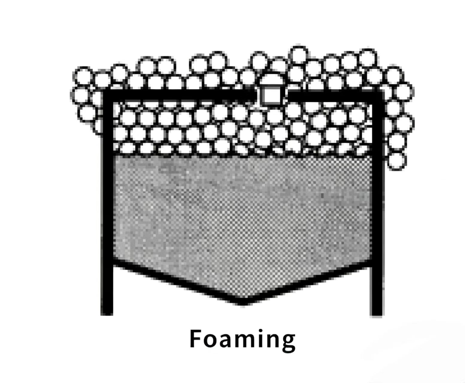
Figure 3-18 Air in the hydraulic system. Foam on the reservoir surface (left) or pump noise (right) both indicate air ingestion problems.
The biggest problem with hydraulic oil in service is contamination. Contaminants can be water, air, or solid particles — solid particles are the most common and most damaging.
Solid contaminants can block control valve orifices, cause moving parts to seize, accelerate wear, and catalyze oil oxidation.
A contaminant is any insoluble substance in the oil. Contaminants enter the system in many ways: during manufacture, assembly, storage, and transport of system components; from the external environment through worn cylinder rod seals or a failed reservoir breather; and from the system itself — worn internal parts generate metal particles continuously. Contamination never stops.
No chemical additive can remove contaminants from oil or prevent them from entering. The goal of good system design and maintenance is to keep contamination from entering, and removing contamination from the oil is the responsibility of filters and the maintenance team.
The naked eye cannot determine contamination level reliably. Viewing oil in a glass flask under light is not an accurate contamination check — many particles harmful to hydraulic systems are too small to see. Accurate contamination assessment requires laboratory analysis.
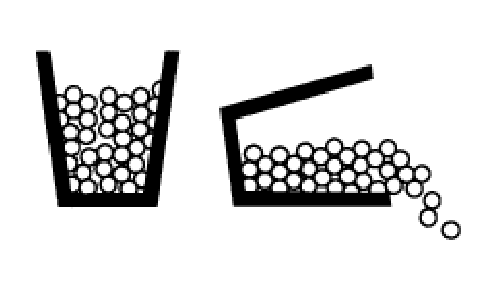
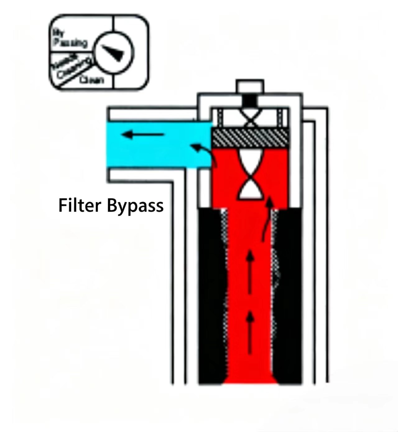
The system filter's blockage indicator provides another way to check contamination. If the filter is correctly sized for the system and the indicator is working properly: a "clean" indication means the oil is clean enough for the system; a "needs servicing" indication means the filter needs maintenance or replacement; if the indicator shows bypassed, the oil is very dirty and the filter needs immediate service.

Figure 3-19 Filter condition indicator. "Clean" (top): oil is acceptable. "Service required" (middle): service or replace the element. "Bypassed" (bottom): oil is very dirty — service immediately.
As mentioned, hydraulic oil has multiple functions in the system and contains various additives to support those functions. It deserves special attention during storage, transport to the reservoir, and throughout system operation.
During storage, the key is keeping the oil in the best possible condition. Contamination of oil in storage drums is not only wasteful — it can also supply the system with degraded oil and compromise reliability.
Drums should be stored in a clean, dry location. Drums stored outdoors should be laid on their sides to prevent water from accumulating on the top and seeping in through the bung seal.
Before starting to transfer oil, clean the drum lid, then prepare all necessary tools and equipment: flexible hose, transfer pump, funnel, reservoir fill filter, and clean hands. Check that the brand name and viscosity on the drum match what is required. Not all hydraulic oils contain the same additives, so it is recommended not to mix oils from different suppliers unless the supplier authorizes it.
Once the oil is in the system, maintain and monitor it at the specified intervals. Oil maintenance includes: topping up to minimum level (use the same oil or one compatible with the existing oil), handling leaks, and changing the filter element.
Changing the filter element regularly is very beneficial. Contamination is extremely harmful to the oil because it catalyzes oxidation, especially when the contaminant particles are iron, lead, or copper. Filters remove most contamination from the flow, but cannot purge contamination completely from the system — they only maintain the oil. If the filter indicator warns but is not serviced promptly, large amounts of unfiltered contamination bypass downstream, affecting components, and contaminants trapped in the dirty element remain in the system, continuing to catalyze oxidation.
Mesh-type filter elements can be cleaned and re-used. The thoroughness of cleaning depends on how carefully the cleaning is done, not on the cleaning method itself.
Common method: soak in clean solvent or hot soapy water, then blow clean with compressed air. Using a soft brush (new paint brush) helps clean the mesh. Never use wire brushes or abrasive materials. After cleaning, hold the element up to light and inspect — gray or black areas indicate the element needs further cleaning.
Ultrasonic cleaning is more expensive but more convenient: place the dirty element in the ultrasonic cleaner for a set time, then remove it clean and ready to re-use. Filter elements rated 40 μm or finer should be cleaned with an ultrasonic cleaner to effectively restore their service life.
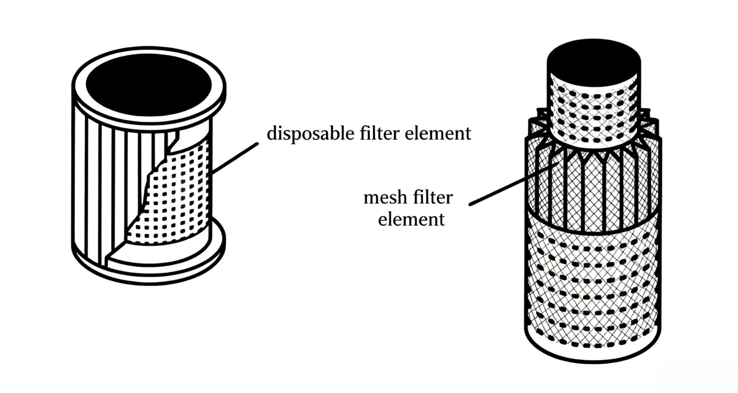
Figure 3-20 Cleaning a mesh filter element. (Left) Ultrasonic cleaner for fine elements. (Right) Holding the clean element up to light to check for remaining blocked areas.
KEY CONCEPTS - CHAPTER 3
|
Concept |
Key Fact |
Practical Implication |
|
Viscosity |
Resistance to flow; drops with heat, rises with cold/pressure |
Must stay in 150-250 SUS (32-54 cSt) @ 100F for most systems |
|
Viscosity Index (VI) |
How stable viscosity is across temperature range |
VI >= 90 required for modern hydraulic systems |
|
Pour point |
Lowest temperature at which oil will still flow |
Must be at least 20F below minimum startup temperature |
|
Oil film / lubricity |
Ability to form and maintain a film between surfaces |
Critical at startup and high pressure — AW additives help |
|
Additive types |
WR (oiliness), AW (anti-wear), EP (extreme pressure) |
Match additive to pressure range; do not mix incompatible oils |
|
Oxidation |
Oil reacts with oxygen — produces acids, sludge, varnish |
Use R&O oils; keep temperature down; eliminate air bubbles |
|
Water contamination |
Promotes rust and accelerates oxidation |
Visual test: cloudy = 0.5% water; milky = 1% water |
|
Contamination |
Solid particles — #1 cause of hydraulic failures |
Maintain filters; inspect indicator regularly; change oil as needed |


Welcome to HOVOO, a Chinese seal factory. Production of PU, Rubber and PTFE seals. The seals include O-ring, piston seal, rod seal, Gray ring and gas seal.


 EN
EN
 AR
AR CS
CS DA
DA NL
NL FI
FI FR
FR DE
DE EL
EL IT
IT JA
JA KO
KO NO
NO PL
PL PT
PT RO
RO RU
RU ES
ES SV
SV TL
TL IW
IW ID
ID LV
LV SR
SR SK
SK VI
VI HU
HU MT
MT TH
TH TR
TR FA
FA MS
MS GA
GA CY
CY IS
IS KA
KA UR
UR LA
LA TA
TA MY
MY