33-99No. Mufu E Rd. Gulou District, Nanjing, China [email protected] | [email protected]
33-99No. Mufu E Rd. Gulou District, Nanjing, China [email protected] | [email protected]

The core of seal design is to make sure that, through the combined effects of structure, tolerances, materials, and other factors, the product blocks all leak paths throughout its entire service life.
If you only check the seal when it is brand new and ignore things like seal ring tolerances, part tolerances, or how the seal performs after aging, you can easily get leaks later. You must consider these factors right from the beginning of design.
Public information divides seals into static seals and dynamic seals (whether there is relative movement between the seal and the parts when it is working). The design focus is very different for each. This article only talks about static seals.
1. Sealing Principle and Failure Modes
2. Seal Ring Structure Design
1. Failure Modes in Different States
2. Contact Pressure and Contact Length under LMC
3. Fill Rate and Local Stress under MMC
3. Weather Resistance of Seal Rings
1. Definition of Compression Set
2. How Compression Set Relates to Pressure (Compression Rate), Temperature, and Aging Time
3. Quick Evaluation Method After Aging
4. Scope of This Article and Future Topics
A product forms a seal because the elastomer (seal ring) is pressed against the contact surface and blocks gas or liquid from passing through.
From the leak path point of view, seal failure has two main forms:
• Interface leak: Happens between the seal ring and the contact surface when the fit is not good enough. Fluid flows along the interface or gap.
• Material permeation: Gas or liquid molecules pass through the rubber or plastic material itself at the molecular level.
In real engineering, the positive-pressure bubble test usually catches big interface leaks more easily. Insulation failure after soaking is better for judging whether the whole product leaks at the system level.
Important note: Test results do not automatically tell you the exact failure mechanism. For example, a product may show no bubbles under positive pressure but fail insulation under negative pressure. This does not prove it is material permeation — it could still be interface leak, local defects in the seal ring, or another path.
Public design guides all stress that when designing a seal ring you must look at compression amount, groove fill, stretch/installation state, surface finish, and tolerances together. Too little compression means poor contact; too much compression can speed up permanent deformation, make assembly force too high, or cause local damage.
For engineering design, you can use finite element analysis (FEA) to simulate the seal ring under stretch, assembly, etc., and judge reliability with key numbers. The important review items are below.
Note: These numbers are engineering proxy indicators, not direct measurements of leakage itself.
During structure review, first check whether obvious failure modes appear under different size combinations and assembly states, such as:
• Seal lip collapse
• Curling or pinching
• Local extrusion
• Clear abnormal stress concentration
This step tells you whether the seal is still in normal working condition. Even if the nominal compression rate looks okay, if the seal lip collapses or folds under extreme assembly, reliability can still drop.
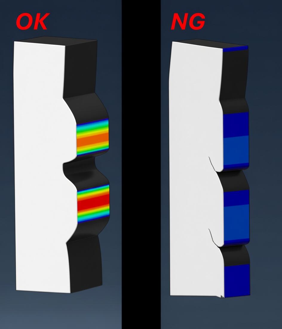
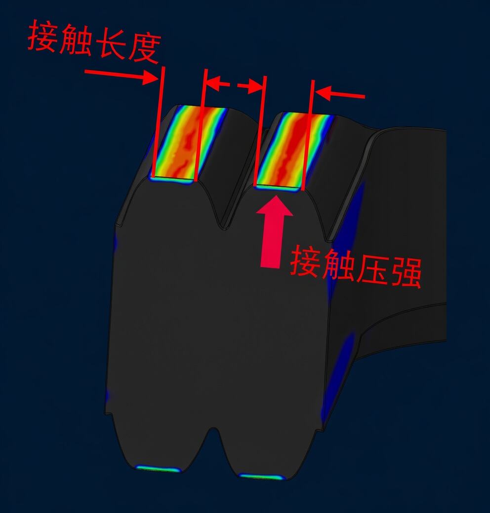
For static seals, LMC (seal ring size at tolerance minimum, groove gap at tolerance maximum) is often the weakest moment, because the combination makes contact pressure and contact length drop more easily.
In the connector field, experience shows that for silicone rubber the initial design should aim for positive pressure >500 kPa and contact length >0.6 mm. This is a reference value that can meet 28 kPa air-tightness after 1008 h at 125°C (roughly equal to 3 m water depth).
Extra notes:
① If needed, also consider deformation of the mating parts under force.
② Contact pressure and length are macro-level checks; at the micro level you still need to think about leak channels formed by surface roughness.
Under MMC the seal ring is more likely to be over-compressed. Focus on:
• Whether the cross-section fill rate is too high (must stay below 100%).
• Whether local stress exceeds what the material can handle (must stay below the rubber's tensile strength) and shows crushing tendency.
• Whether there is risk of extrusion.
The earlier part covered the seal ring's performance when new, and FEA can give fairly accurate results for that.
But rubber materials suffer permanent compression set, stress relaxation, thermal aging, and property drop over time, so the sealing interface gradually loses its original contact force.
Passing initial checks does not mean it will still be reliable at the end of life. You must consider aging factors from the start of design.
Compression set is a key index for judging how well rubber keeps its elasticity after long-term compression.
It means that after the seal ring is compressed and aged for a long time, when you remove the pressure it cannot fully spring back to its original shape. The bigger the compression set, the worse the recovery ability and the higher the risk of losing effective seal contact at the end of life.
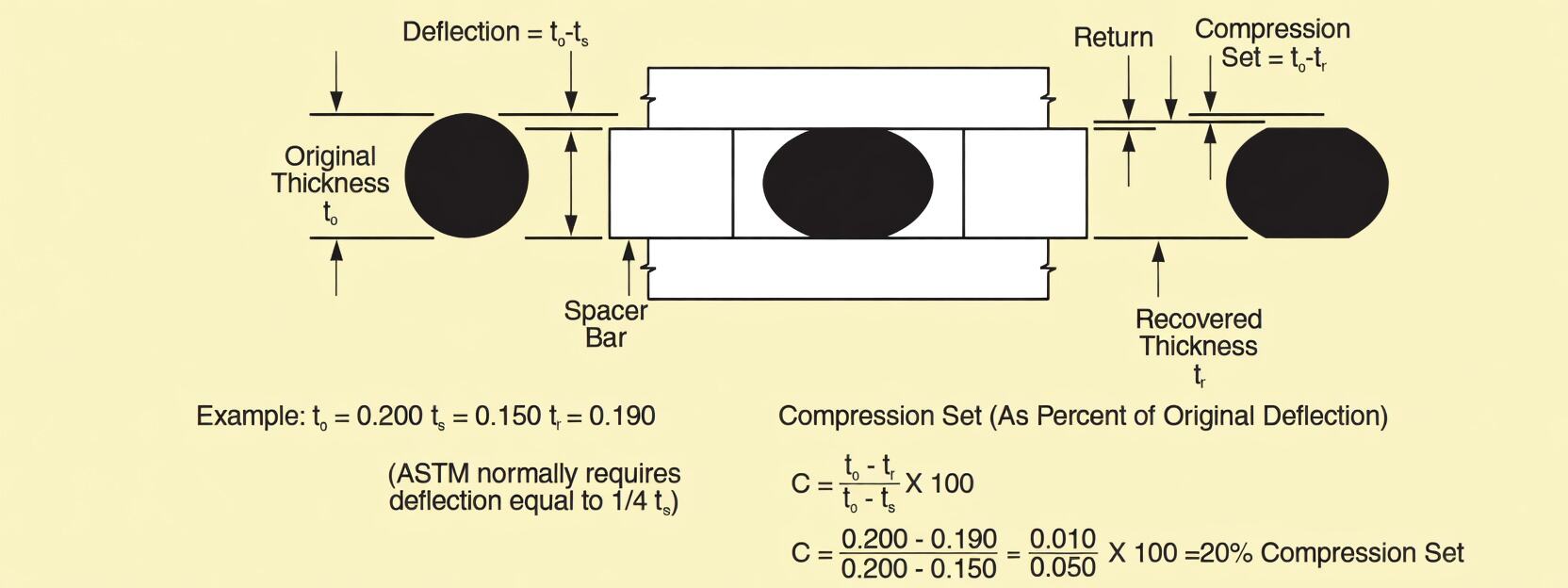
(The article shows a diagram of compression set here.)
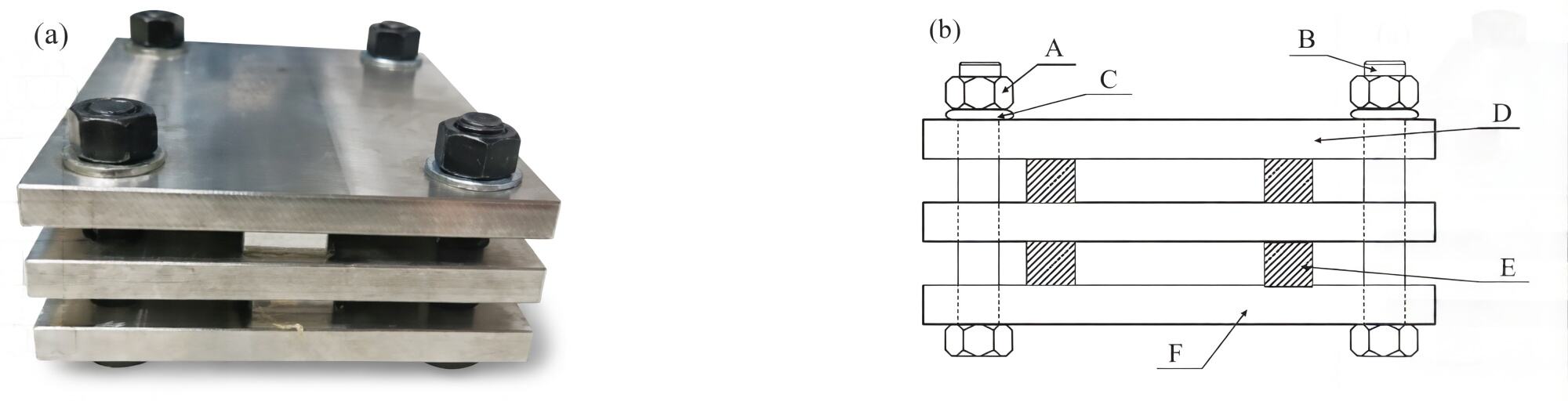
(The article shows the standard industry test fixture for seal ring compression set — a standard-size rubber block placed between plates.)
Qualitatively, the three main factors are pressure (compression rate), temperature, and time.
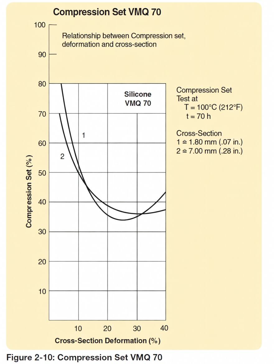
(The article shows a graph of VMQ silicone rubber compression set vs. compression rate. For VMQ, too little or too much compression is not the best for long-term performance.)
(Note: When compression is very light, the "percentage" compression set number can look very high.)
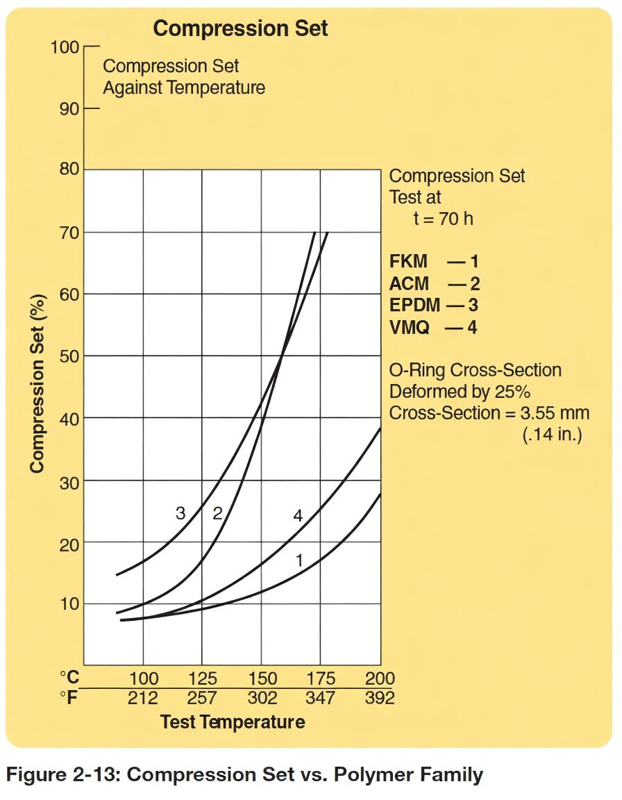
(The article shows graphs of compression set after aging at different temperatures — higher temperature makes recovery worse.)
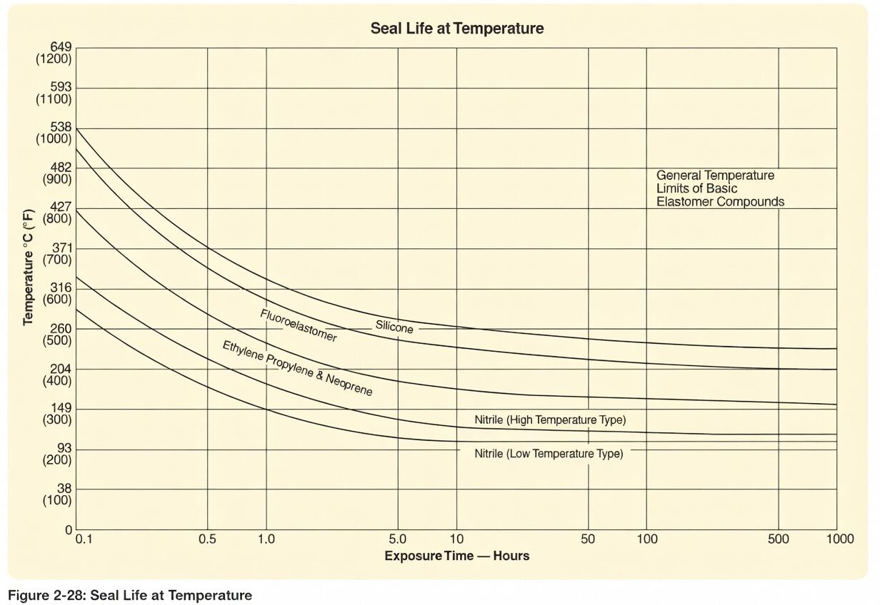
(The article shows approximate service life of different seal materials at various temperatures — for reference only.)
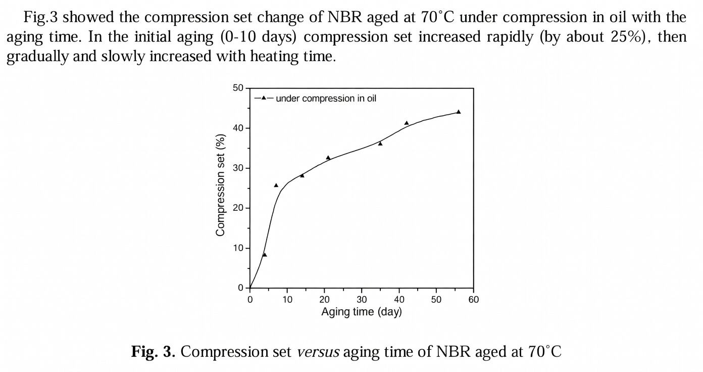
(The article shows a graph of NBR rubber compression set vs. aging time.)
In engineering practice, you can plug the aged compression set value back into the initial design to quickly check whether you have enough margin and judge the failure risk at end of life.
Example: If the initial design compression rate is 10%, but after 1008 h at 125°C the compression set becomes 17%, then after aging the seal is very likely to fail. You should increase the initial compression rate or choose a rubber with better compression set performance.
Note: This method is good for quick checks or trend judgment, not for direct prediction of final leak rate.
This article gives a qualitative framework for seal design, but many topics are not covered yet, such as the relationship between surface roughness and sealing, the effect of low temperature on seal performance, quantitative methods for leak rate, and building temperature-aging fitting models.
[1] Parker Hannifin Corporation. Parker O-Ring Handbook: ORD 5700[M]. Cleveland, OH: Parker Hannifin Corporation, 2021.
[2] QIAN Y H, XIAO H Z, NIE M H, et al. Lifetime prediction of nitrile rubber under compression stress in transformer oil[C]//Proceedings of the 2016 5th International Conference on Measurement, Instrumentation and Automation (ICMIA 2016). Paris: Atlantis Press, 2016: 189-194. DOI: 10.2991/icmia-16.2016.35.

Welcome to HOVOO, a Chinese seal factory. Production of PU, Rubber and PTFE seals. The seals include O-ring, piston seal, rod seal, Gray ring and gas seal.


 EN
EN
 AR
AR CS
CS DA
DA NL
NL FI
FI FR
FR DE
DE EL
EL IT
IT JA
JA KO
KO NO
NO PL
PL PT
PT RO
RO RU
RU ES
ES SV
SV TL
TL IW
IW ID
ID LV
LV SR
SR SK
SK VI
VI HU
HU MT
MT TH
TH TR
TR FA
FA MS
MS GA
GA CY
CY IS
IS KA
KA UR
UR LA
LA TA
TA MY
MY