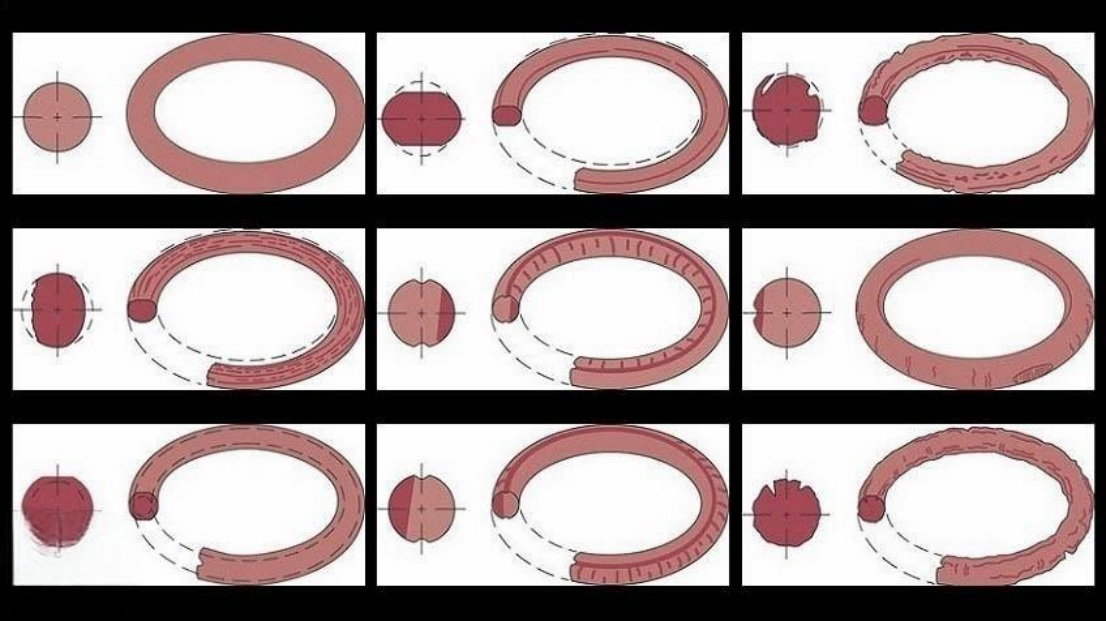
A brand-new O-ring that leaks right after installation is often not a quality problem with the O-ring itself, but a result of damage that occurred during the installation process. Scratches, twisting, over-stretching, nicks from burrs, sharp edges, or thread damage can already have created a leak path before the seal has done any work.
An O-ring relies on an intact, continuous cross-section under proper compression to seal. As long as installation causes scratches, twisting, over-stretching, nicks from burrs, insufficient chamfer, improper lubrication, or damaged thread protection, the seal can leak immediately.
1. Why Does a New O-Ring Leak Right After Installation
Installing an O-ring is not simply a matter of getting it into place — it must simultaneously satisfy several conditions:
Correct dimensions: ID, cross-section, hardness, and material must match the design requirements.
Correct sealing groove condition: the groove bottom, groove walls, chamfer, and surface roughness must be free of abnormalities.
No damage during the installation process: no cuts from sharp edges, burrs, scratches, or bore-opening damage.
Correct post-installation posture: no twisting, curling, localized thinning, or local bulging.
Correct lubrication: the lubricant must be compatible with the rubber and the media, and used in the proper amount.
Correct compression amount: after assembly the O-ring must be compressed continuously and evenly — neither over-squeezed nor under-compressed.
A common scenario in the field is: the O-ring was fine when it left the factory, but during passage over threads, steps, bores, or insufficient chamfers it was cut with a fine nick; the leak is invisible when looking at the outside of the finished assembly, but shows up as soon as pressure is applied.
So aftermarket troubleshooting should not stop at asking "is the new O-ring's quality bad?" — it should also ask: did the O-ring's installation path pass over any sharp edges, threads, burrs, holes, or groove edges? Was it lubricated during installation? Was a protective sleeve used? Was it forcibly pried or dragged into the bore?
2. Typical Installation Errors and Their Consequences
Installation Error |
Symptom on Site |
Problem Caused |
Common Cause |
Installation scratch |
O-ring surface shows straight, arc-shaped or oblique scratches |
Obvious leakage right after assembly |
Metal burrs, sharp edges, threads scraping the ring |
Twisting |
O-ring shows a candy-twist-like spiral pattern inside the groove |
Uneven or insufficient local compression, sealing line discontinuous, leakage worsens after running |
Improper rotation, local over-stretch during assembly |
Over-stretching |
O-ring becomes thinner, deformed, cannot return to original size |
Insufficient compression, sealing force under-delivered, permanent elongation |
No guide tool used, forced tension through a bore/step |
Nick from burrs |
There is a small nick or cut on the removed O-ring |
Forms a direct leak path |
Burrs left at groove opening, bore, or thread that were not cleaned |
Insufficient chamfer |
O-ring cut at entry into bore or groove opening, damage not immediately visible |
Not immediately visible, but leaks eventually |
Lead-in chamfer too small, sharp edge |
Lubrication error |
Assembled dry or with insufficient lubrication; or incompatible lubricant causes the rubber to swell or soften |
Assembled dry causing scoring; incompatible lubricant reduces material strength |
Compatible lubricant not used, or over-applied causing foreign matter contamination |
Insufficient thread protection |
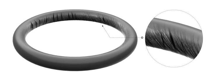
Continuous helical scratches on inner side of the O-ring |
New O-ring cut by thread crests |
O-ring pulled directly over external or internal threads |
3. What Must Be Checked Before Assembly
3.1 Inspect the O-Ring Itself
Look at the O-ring before assembly — do not just pick it up and install it directly.
Key checks:
- Whether the surface has cuts, cracks, indentations, missing rubber, flash, or burrs.
- Whether the cross-section is uniform, with no local thinning or local flattening.
- Whether metal shavings, sand particles, dust, or sealant residue are adhering to it.
- Whether the dimensions match: ID, cross-section diameter, material, and hardness must be consistent with the drawing or maintenance manual.
- Whether aged, hardened, sticky or brittle stock inventory items are being used.
Note: never use a sharp metal tool to pick up an O-ring. A metal screwdriver, hook, or blade can very easily leave a fine scratch during removal, and that scratch can turn directly into a leak point after assembly.
Recommended tools:
- Plastic installation rods.
- Nylon tools.
- Round-tip disassembly hooks.
- Dedicated O-ring installation tools.
3.2 Inspect the Sealing Groove
A sealing groove is not acceptable just because the dimensions are roughly right — the groove opening, groove bottom, and groove wall condition all affect the seal.
Inspection points:
- Whether burrs, metal shavings, rust, old rubber residue, or contaminants are inside the groove.
- Whether the groove opening has sharp edges.
- Whether the chamfer is complete and smooth.
- Whether the groove bottom has scratches, dents, or impact marks.
- Whether the groove wall has steps, scoring, or corrosion pits.
- Whether debris from an old O-ring remains in the groove.
This can be checked by feel, but do not rely on touch alone — many small burrs are not obvious to the finger but are still sharp enough to cut rubber.
A simple field method: lightly wipe the groove opening and bore with a cotton swab or non-woven cloth. If fibers catch on it, this usually indicates a burr or sharp edge is present and needs to be addressed.
3.3 Inspect the Installation Path
This step is the one most easily overlooked.
From when the O-ring leaves your hand to when it reaches its final sealing position, every location it passes through is called the installation path. It is not enough to only check the sealing groove — you must also check what the O-ring will "encounter along the way."
Key checks:
- External threads.
- Internal thread openings.
- Keyways.
- Oil holes.
- Cross holes.
- Steps.
- Retaining ring grooves.
- Sharp edges.
- Bore openings without a chamfer.
- Cross holes with cutting burrs.
Many leaks are not caused by the sealing groove itself, but rather because the O-ring was already cut by threads, holes, bore openings, or sharp edges before it even reached the sealing groove.
4. How to Use Lubrication Correctly
4.1 Why Lubrication Is Necessary
The purpose of lubrication is not to make the O-ring look more slippery — it is to reduce assembly friction and prevent the O-ring from being pulled, twisted, rolled, or sheared.
Without lubrication, the following are likely:
- The O-ring gets dragged by dry friction.
- Installation scratches appear on the surface.
- The O-ring twists locally.
- Assembly force becomes excessive, causing over-stretching.
- Damage is even more likely with a low-temperature or higher-hardness O-ring.
So unless the process explicitly prohibits it, O-ring installation should normally use compatible lubrication.
4.2 The Lubricant Must Be Compatible
Lubricants cannot be used arbitrarily. An incompatible lubricant can cause the rubber to swell, soften, crack, or degrade performance.
Principles:
- The lubricant must be compatible with the O-ring material.
- The lubricant must be compatible with the working media.
- The lubricant must be compatible with the equipment system.
- In hydraulic systems, the system's own working oil is often used as the assembly lubricant.
- In pneumatic systems, use grease that is compatible with the sealing material.
- EPDM, silicone rubber, fluoroelastomer, nitrile rubber and other materials have different compatibility with oils and solvents — do not judge based on experience.
This must be emphasized in aftermarket training: not every grease can lubricate every O-ring. An incompatible lubricant can be worse than no lubrication at all.
4.3 Use the Right Amount of Lubricant
Correct practice:
- Form a thin, continuous lubricating film on the O-ring surface.
- At the installation groove, lead-in chamfer, and installation path, apply an appropriate amount.
- Do not apply it as thick globs of grease.
- Do not let the lubricating grease carry metal shavings, sand particles, or dust.
- Do not apply it with a contaminated brush or dirty gloves.
Problems with excessive lubrication:
- Absorbs contaminants.
- Interferes with assembly positioning.
- In some hydraulic circuits, may cause hydraulic lock failure.
- When incompatible with the media, accelerates seal failure.
-
During later disassembly inspection, can mask the true damage, making diagnosis harder.
5. How to Prevent Damage from Sharp Edges, Burrs, and Threads
5.1 Burrs Are the O-Ring's "Invisible Blade"
There are three types of locations O-rings fear most:
- Untreated sharp bore edges.
- Burrs left after machining that were not removed.
- Thread crests and thread entry points.
These locations look like minor burrs, but for a rubber seal they act as a blade.
Typical consequences:
- A fine scratch is pulled across the O-ring surface.
- A V-shaped nick is cut into the cross-section.
- Externally the ring looks fine, but a leak path already exists internally.
- The higher the pressure, the more easily the nick is torn open.
5.2 A Lead-In Chamfer or Rounded Edge Is Mandatory
Wherever an O-ring passes through a bore opening, shaft shoulder, or groove, there must be an appropriate lead-in chamfer or rounded edge.
Functions of the chamfer:
- Allows the O-ring to smoothly enter the sealing position.
- Avoids the ring being cut by a right-angle edge.
- Reduces assembly resistance.
- Reduces local stretching and twisting.
Incorrect practices:
- Pushing the O-ring directly across a right-angle bore opening.
- Forcing it through with brute pressure.
- Assuming "rubber is soft, it will squeeze through if you push a bit harder."
- A chamfer exists in shape but still has burrs on its edge.
Correct requirement: the chamfer must not only "have a shape" — it must also be free of burrs, free of sharp edges, and have a smooth surface.
5.3 Threads Must Be Protected
This is one of the most common problems seen in the aftermarket field.
If an O-ring must pass over external threads, internal thread openings, or threaded connectors, thread protection must be used.
Options include:
- Thread protection sleeves.
- Smooth lead-in guide sleeves.
- Tapered guide sleeves.
- Thin-wall installation sleeves.
- Temporary protective film.
- Dedicated assembly tooling.
Incorrect practices:
- Pulling the O-ring directly over external threads.
- Forcing it over thread crests with fingers.
- Assuming that applying oil means protection can be skipped.
- Wrapping it casually with tape, but the tape's edge is raised or wrinkled and instead scratches the O-ring.
How to tell: when a leaking new O-ring is removed, if there is a ring of fine, evenly-spaced horizontal scratches on its inner side, or diagonal cut marks, the common cause is exactly this — insufficient thread protection.
6. How to Avoid Twisting
6.1 Why Does a Twisted O-Ring Leak
An O-ring is designed to bear even compression across its cross-section within the groove.
If it gets installed twisted into a candy-twist shape, the following will occur:
- Local over-compression.
- Local under-compression.
- A discontinuous sealing line.
- Increased friction and abrasion during operation.
- A leak gap appears when pressure changes.
Leakage from twisting is sometimes not immediate or heavy — it can present as:
- Assembled fine at first, but starts leaking after running for a while.
- No leak at low pressure, leaks at high pressure.
- No leak at rest, leaks after actuation.
- Leaks after temperature rises.
- When disassembled, a helical mark is found on the O-ring.
6.2 How Does Twisting Usually Occur
Common causes:
- Dry installation.
- Insufficient lubrication.
- Rolling the O-ring into the groove like a rubber band.
- Stretching only one side, causing uneven expansion.
- Not tidying the O-ring after installation.
- Groove is too deep, causing high resistance after installation and the posture is not confirmed.
- Large cross-section diameter O-ring, high assembly resistance.
- Narrow assembly clearance, fingers cannot confirm posture.
- No guide tool used for a dynamic seal assembly.
6.3 Correct Practice
During installation you should:
- Expand it evenly, not stretch from just one point.
- Not let the O-ring roll into the groove.
- After installation, lightly straighten it around the full circumference.
- Use mold lines or surface markings to judge whether installation is correct.
- For large-size O-rings, have two people cooperate on installation.
- For long installation paths, use a guide cone or installation sleeve.
- Lubricate before insertion — do not force it in dry.
Check after installation:
- Whether the O-ring sits flat in the groove.
- Whether there is local bulging.
- Whether there is local whitening or thinning.
- Whether one section sits differently than others.
- Whether it maintains a natural state within the groove.
- Whether a spiral surface pattern is present.
Key reminder: an O-ring is not "in" just because it fits into place — you must confirm it has no twist inside the groove.
7. How to Avoid Over-Stretching
7.1 Why Does Over-Stretching Cause Leakage
If an O-ring is stretched too much, two problems occur:
First, the cross-section diameter becomes thinner. When the O-ring is elongated, its cross-section becomes thinner, and the actual compression amount decreases, so sealing force is insufficient.
Second, it cannot fully recover. If the stretch exceeds the material's and structure's allowable range, the O-ring may not be able to fully recover, becoming "loose" or "thin" after installation.
Consequences include:
- Insufficient compression amount after installation.
- O-ring cannot press tightly against the sealing face.
- Leakage at low-pressure start-up.
- Being extruded out of the groove during operation.
- Local tearing occurs.
- Service life is significantly shortened.
7.2 Which Scenarios Are Prone to Over-Stretching
Common scenarios:
- The O-ring must be fitted over an oversized shaft shoulder.
- No installation cone is available on site, forcing manual stretching.
- Using a screwdriver or hook to pry the O-ring open.
- A small-size O-ring being fitted over a large-diameter part.
- The ID selected is too small, so oversized stretching is used to compensate.
- In a low-temperature environment where the rubber has hardened, its rebound is slow.
- A maintenance technician, to save time, stretches it over multiple steps in one go.
7.3 Correct Practice
Should use:
- A guide cone.
- An expansion sleeve.
- An installation sleeve.
- Smooth, edge-free assist tools.
- A segmented, even push-in method.
Principles:
- Only stretch enough to clear the installation obstacle.
- Do not maintain the stretched state for a long time.
- Do not use a sharp tool to hook and pull.
- After installation, let the O-ring return to its natural position on its own.
- If whitening, cracking, obvious thinning, cross-section changes, or a failure to return to shape after removal occurs, replace the ring.
- Do not install based on the experience of "stretch it a bit more, it'll still work."
Aftermarket judgment key points: if a new O-ring becomes noticeably loose after installation, the OD becomes visibly larger, the cross-section becomes thinner, or after removal it cannot recover its original shape, over-stretching or an incorrect size selection should be suspected first.
8. How to Judge Whether Damage Was Caused by Installation During Teardown Inspection
When a customer reports "the new O-ring leaked right after installation," do not jump to a conclusion — it is recommended to follow this process for teardown inspection.
8.1 Preserve Evidence First
Before teardown:
- Photograph and record the installation position.
- Record the timing of the leak: immediately after installation, after running, after pressure increase, after temperature rise.
- Record the media, pressure, temperature, and motion status.
- Record whether lubrication was used during installation.
- Record whether the ring passed over threads, bore openings, or sharp edges.
- Do not clean the removed O-ring until damage can be seen — do not stretch, pry, or use a sharp tool to remove it again, to avoid secondary damage.
8.2 Examine the O-Ring Wound Pattern
Damage Pattern |
Possible Cause |
Straight-line cut, oblique cut |
Sharp edge, thread, bore opening, or burr scratch |
A ring of fine scratches |
Scraped when passing over threads or a rough bore opening |
Local V-shaped nick |
Burr, sharp corner, hard particle cut |
Spiral scratch marks |
Assembly twisting, rolling, dragging |
Local whitening, thinning |
Over-stretched or forcibly expanded |
Cross-section badly flattened |
Over-compression, groove dimension abnormality |
Surface swelling, softening, tackiness |
Lubricant or media incompatibility |
Local wear |
Skewed dynamic seal assembly, insufficient lubrication or rough surface |
8.3 Trace Back the Installation Path
After finding the O-ring's wound, trace back where it could have been damaged.
Key checks:
- Threads the O-ring passed over.
- Bore opening crossing edges.
- Sealing groove entry point.
- Shaft shoulder steps.
- Retaining ring grooves.
- Oil hole edges.
- Chamfer edges.
- Assembly tool contact positions.
Often, the direction of the cut on the O-ring can be used to infer the damage location:
- Diagonal scratching: commonly seen when it was scraped by a bore opening or thread during a push-in.
- Circumferential scratching: commonly seen during rotational assembly or when passing over a shaft.
- A local deep nick: commonly caused by a single burr or sharp point.
- Multiple small scratches: commonly caused by a rough installation path or contamination particles.
9. Standard Operating Procedure for Assembly Personnel
Step 1: Confirm the Specification
Confirm:
- O-ring specification.
- Material.
- Hardness.
- Batch.
- Applicable media.
- Whether it is the design-specified model.
Prohibited:
- Substituting with a similar-sized ring.
- Installing with an unclear material.
- Temporarily reusing an old ring.
- Mixing different-material O-rings together.
Step 2: Clean the Sealing Groove and Installation Path
Must remove:
- Metal shavings.
- Burrs.
- Dust.
- Old rubber.
- Sealant residue.
- Rust particles.
- Hard contaminants.
Confirm after cleaning:
- No foreign matter in the groove.
- No burrs on the chamfer.
- No sharp edges on the bore opening.
- Threads are protected.
- The installation tool is clean.
Step 3: Address Sharp Edges and Chamfers
Do not assemble directly if any of the following are found:
- Burrs at the groove opening.
- A rough bore opening.
- Chamfer is discontinuous.
- Sharp thread entry point.
- Raised edge at a cross hole.
- Impact marks at the step edge.
Handling method:
- Remove burrs.
- Add a chamfer.
- Polish sharp edges.
- Clean off residual filings.
- Re-inspect.
Step 4: Apply Thread Protection
When the O-ring passes over threads, protective measures must be used.
Recommended:
- Protective sleeve.
- Guide sleeve.
- Tapered sleeve.
- Smooth thin-wall sleeve.
- Dedicated assembly tooling.
Not recommended:
- Pulling it directly over threads.
- Forcing it with a hard push.
- Prying with a sharp tool.
- Wrapping casually with rough tape.
- Assuming applying oil can substitute for protection.
Step 5: Correct Lubrication
Lubrication requirements:
- Use a compatible lubricant.
- Apply thinly.
- Apply evenly.
- Do not mix in particles.
- Both the O-ring and the installation path may be appropriately lubricated.
- Assemble immediately after lubrication to avoid picking up dust.
Prohibited:
- Using an unidentified grease.
- Using dirty grease.
- Forcing it in dry.
- Over-lubricating.
- Using a solvent incompatible with the rubber to clean it before direct installation.
Step 6: Smooth Installation
During installation:
- Expand evenly.
- Avoid a single-point hard pull.
- Avoid rolling it in.
- Avoid twisting.
- Avoid using a sharp tool.
- If resistance is encountered, do not force it — stop and check for sharp edges, misalignment, or a specification error.
The correct motion is "guide, push in, straighten, confirm" — not "pull, force, or press hard."
Step 7: Post-Installation Inspection
After installation, confirm:
- The O-ring is fully seated in the groove.
- No twisting.
- No local thinning.
- Not extruded out.
- No new scratches on the surface.
- No abnormal resistance when the mating part is engaged.
If resistance suddenly increases when closing the assembly, do not force it to lock. This may indicate the O-ring has been pinched, misaligned, cut, or sheared.



 EN
EN
 AR
AR CS
CS DA
DA NL
NL FI
FI FR
FR DE
DE EL
EL IT
IT JA
JA KO
KO NO
NO PL
PL PT
PT RO
RO RU
RU ES
ES SV
SV TL
TL IW
IW ID
ID LV
LV SR
SR SK
SK VI
VI HU
HU MT
MT TH
TH TR
TR FA
FA MS
MS GA
GA CY
CY IS
IS KA
KA UR
UR LA
LA TA
TA MY
MY
