33-99No. Mufu E Rd. Gulou District, Nanjing, China [email protected] | [email protected]
33-99No. Mufu E Rd. Gulou District, Nanjing, China [email protected] | [email protected]

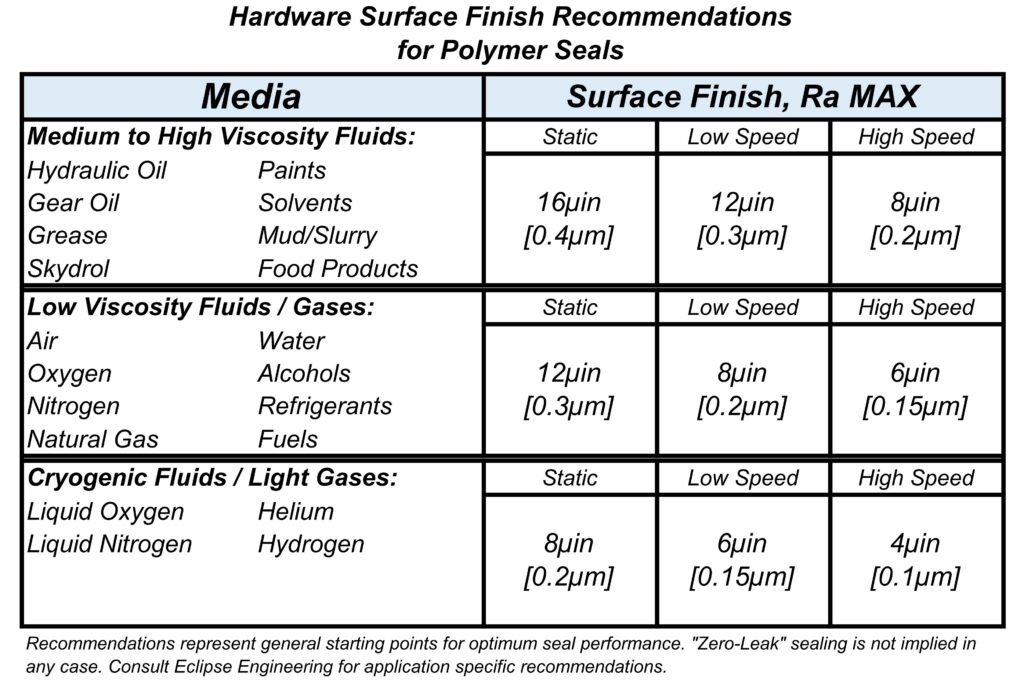
The requirement for O-ring sealing-face roughness cannot be written with just one Ra — at minimum simultaneously control: Ra/Rz or Rmax, machining-line direction, scratches/burrs/rust spots, plating layer integrity, chamfer amount. ISO 3601-2:2025 clearly points out the surface roughness of the O-ring groove and mating component significantly affects sealing and dynamic sealing performance, and requires the sealing working face must be free of scratches, burrs, dents, tool marks, thread and other defects, and also recommends controlling the surface material ratio Rmr, not just Ra.
O-ring sealing relies on pre-compression and media pressure forming contact stress on the metal surface. If the sealing face is too rough, surface peak-valleys will form micro-leak channels; if the surface has transverse scratches, sand holes, plating layer flaking, or knife-mark scoring, the O-ring may not be able to fully compress-close these continuous channels even if the size and material are correct.
But the surface also isn't the smoother the better. Especially in reciprocating or rotary dynamic seals, over-polishing may instead destroy the lubricant oil-film storage capacity, causing dry friction, adhesion, and accelerated wear. ERIKS' O-ring design material points out that dynamic-seal contact face too smooth may lower lubricant retention and increase excessive wear, and general dynamic O-ring seal face below about 0.15 μm Ra is generally not recommended, because the surface needs micro oil-film storage capability.
The table below gives commonly-used engineering design points. Unit is μm. Different standards and manuals use Rz, Rmax, Rt and other different parameters, cannot be directly interchanged; look up the applicable measurement standard and parameters clearly before applying.
Operating Condition/Face |
Recommended Roughness, Engineering Point |
Explanation |
Static seal, general non-dynamic condition, sealing contact face |
Ra ≤ 1.6; Rz/Rmax approx. ≤ 6.3 |
General flange, end-face static seal, radial static seal can use this grade; Parker's static seal recommendation gives, non-pulsed contact face Ra 1.6, Rmax 6.3. |
Static seal, pulsating pressure, gas, low-viscosity media, higher seal requirement |
Ra ≤ 0.8; Rz/Rmax ≤ 1.6–3.2 |
Pulsating-pressure leak paths are more sensitive; Parker's dynamic static seal contact face gives Ra 0.8, Rmax 3.2. |
Static seal groove bottom/groove side |
Ra ≤ 1.6–3.2; Rz/Rmax ≤ 6.3–12.5 |
Groove bottom and side are not all-area facing the O-ring extrusion, side wall can afford somewhat looser control than the sealing contact face; Parker's given non-dynamic-seal-matching groove face and side, and ISO 3601-2:2025's recommended sealing groove face adopts Ra 1.6, Rz 6.3. |
Reciprocating dynamic seal, rod/hole/piston sliding dynamic contact face |
Ra ≤ 0.4; Rz/Rmax approx. ≤ 1.6; not too low, approx. Ra 0.1–0.15 |
Dynamic-seal contact face requirement is notably higher than static seal, ISO 3601-2:2025 requires dynamic mating face given Ra 0.4, Rz 1.6; Parker reciprocating hydraulic seal contact face also gives Ra 0.4, Rmax 1.6. |
Reciprocating dynamic seal, groove bottom/side |
Ra ≤ 1.6; Rz/Rmax ≤ 6.3 |
This mainly prevents O-ring wear, biting, extrusion and disassembly damage; Parker dynamic seal, groove bottom and side gives Ra 1.6, Rmax 6.3. |
Chamfer/lead-in for assembly |
15°–20°; surface chamfer not too rough or with burrs; edge round, no burrs |
ISO 3601-2:2025 requirement chamfer angle 15°–20°, and lead-in edge smoothly rounded, no burrs. |
Rotary condition, O-ring as rotary seal, turn-time friction |
Follow dynamic-seal principles: shaft face Ra 0.2–0.4, heat generation obvious, rubber more easily hardens, wears, and loses elasticity. Rotary O-ring seal applications should generally control compression rate, use lubrication, avoid O-ring circumferential slip, and inspect surface hardness regularly. |
|
There's no relative sliding motion in a static seal, roughness can be somewhat looser than dynamic seal, but for gas, vacuum, low-viscosity liquid or medium/high-pressure sealing, it's recommended to raise to Ra 0.8 μm or finer. COG's O-ring material also lists sealing-zone static seal Ra 1.6/Rz 6.3, dynamic seal Ra 0.4/Rz 1.6, installation lead-in chamfer Ra 1.6/Rz 6.3.
Static seal roughness cannot be too tolerant either. If flash, cutting, or crossing burrs excessive push the O-ring toward the low-pressure side, a leak channel will form. ERIKS' material also points out surface-machining direction is important, e.g. incoming machining marks along the mold-turning path, coarser surface still may be sealed, but sharp-edge scratches through the O-ring will notably raise risk.
The static-seal judgment logic isn't "Ra achieves the mark, done," instead: Ra/Rz achieves + no through-scratch damage + no burrs + plating layer intact + compression amount sufficient + groove not over-filled.
In a reciprocating dynamic seal, the O-ring long stays in continuous sliding contact with the rod, plunger or piston surface, so the sealing face needs to be smooth enough, avoiding wear, while also retaining a slight oil film, avoiding dry friction. Parker's handbook stipulates the reciprocating hydraulic seal contact face be Ra 0.4, Rmax 1.6; the groove bottom and side also use Ra 1.6, Rz 1.6.
Dynamic seal common failure modes are not the O-ring material itself, but the sliding surface having: axial long scratches; helical grinding or lathe-cut lead marks; chrome-plating layer cracking, flaking, raised burrs; knife-marks; port intersection unbeveled; groove-edge burrs; surface over-coarse causing wear, or over-mirror finish causing no oil film.
For hydraulic reciprocating seals, it's recommended dynamic seal fitting surfaces be produced with honing, rolling, polishing and hard-chrome plating, and confirmed the final mirror-finished surface after polishing. ERIKS' material also stresses that dynamic contact face machining quality directly affects O-ring life.
An O-ring can be used for low-speed, short-time, light-load rotary seal, but it's not a typical high-speed rotary seal. Under rotary conditions, the O-ring's inner diameter stays radially frictioned, friction heat is not easily dissipated, and Parker also specially notes the Gough-Joule effect: if the O-ring's inner diameter is smaller than the shaft face, further heating causes shrinkage, and failure manifests as O-ring surface hardening, wear, shrinkage, and eventual leakage. Actual design should use a relatively larger cross-section O-ring, and let the inner diameter stretch rate against the shaft diameter about 1%–3%, decompressing the groove compression.
Rotary O-ring surface requirement is more strict at the dynamic-seal level: shaft face Ra 0.2–0.4 μm, Rz/Rmax controlled at about 1.6 μm, while also avoiding a radial-lead-in machining groove pattern on the shaft, because this class of texture can produce a pump-suction effect, causing leakage. Continuous rotation, high linear speed, high temperature, or unlubricatable operating conditions, should preferentially consider a dedicated rotary shaft seal, PTFE rotary seal, X-ring or dedicated rotary sealing structure, not a general O-ring.
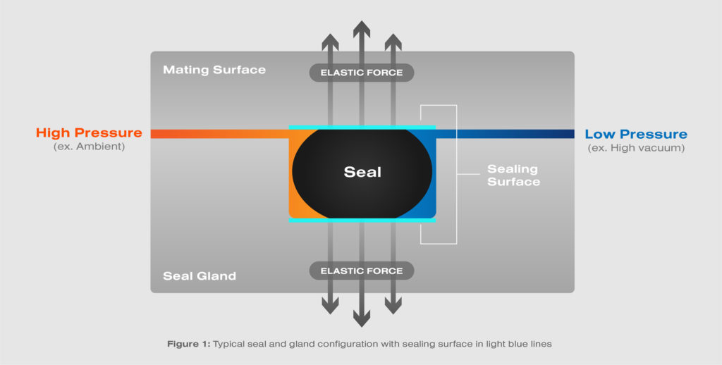
Two surfaces can have the same Ra, but one is a round waveform, the other is sharp peak-and-valley — the latter can cut the O-ring or form a leak channel. Parker's handbook clearly points out Rt and Ra alone are insufficient to judge whether the sealing face is suitable, other parameters like Rp or contact area/load-bearing-area ratio should be considered; ISO 3601-2:2025 also recommends the sealing contact surface's material ratio Rmr maintain 50%–80% under specific conditions.
Therefore, the drawing should not only write:
Ra 1.6
This is not enough. A better writing method is:
Sealing contact face: Ra ≤ 0.4 μm, Rz ≤ 1.6 μm, measured per ISO 21920; no scratches, burrs, dents, tool marks, plating layer flaking; machining lines not allowed to run through the leak direction.
Scratches: even if overall Ra qualifies, a single through-sealing-line scratch can also form a leak. For static seals, focus on whether scratches run through high-low pressure directions; for dynamic seals, any axial or spiral direction linear scratches should be treated as high risk.
Plating: hard chrome, chemical nickel, anodic oxide and coating layers must satisfy the roughness requirement in the final state; plating flaking, pinholes, blistering, raised edges are two problems: one is forming a leak path, the other cuts the O-ring, especially avoiding coating-layer boundaries falling within the sealing band.
Burrs: groove openings, chamfer edges, intersection holes, oil-hole mouths must all be deburred and rounded. ISO 3601-2:2025 clearly requires related zones on the rod/live-plug groove must have no burrs, edge should be smoothly rounded; some surfaces also note radial tool marks are not allowed to be visible.
Chamfer insufficient: the O-ring gets stretched, compressed and passed over the edge during assembly; insufficient chamfer doesn't cause cutting, bruising, twisting or partial cracking during assembly. Lead-in chamfer is generally taken at 15°–20°, edges must be smooth and burr-free, chamfer length determined per the O-ring cross-section diameter.
Sealing contact face A: Ra ≤ 1.6 μm, Rz ≤ 6.3 μm; no through-scratches, burrs, bumps, sand holes, plating layer flaking.
Groove bottom/side face B: Ra ≤ 1.6–3.2 μm, Rz ≤ 6.3–12.5 μm; groove opening deburred.
Lead-in chamfer C: 15°–20°, Ra ≤ 1.6 μm, Rz ≤ 6.3 μm, smooth and burr-free.
Sealing contact face A: Ra ≤ 0.8 μm, Rz ≤ 3.2 μm; key sealing band must not have any visually-identifiable line defects. Increase Rmr or peak-height Rp requirement when necessary, and conduct leak test verification.
Sliding contact face: Ra 0.2–0.4 μm, Rz ≤ 1.6 μm; not lower than approx. Ra 0.1–0.15 μm; no axial scratches, spiral lines, plating flaking, knife-vibration marks.
Groove bottom/side: Ra ≤ 1.6 μm, Rz ≤ 6.3 μm.
Chamfer: 15°–20°, smooth and burr-free; intersection holes must be rounded or avoid the sealing travel.
Only for low speed, short time, sufficiently lubricated condition, shaft face Ra 0.2–0.4 μm, Rz ≤ 1.6 μm; not allowed spiral lead-in machining lines. O-ring should not radially overhang and stretch on the shaft, preferentially use an outer-fitted groove pressure-relief structure. Continuous rotary or high-speed condition should switch to a dedicated rotary seal.
Once leakage occurs, don't first switch to a harder or softer O-ring. It's recommended to check per this order:
Whether the sealing face's Ra/Rz meets the drawing; whether through-scratches, tool marks, sand holes, dents exist; whether the plating layer flakes, blisters, has pinholes, raised edge accumulation; whether the groove opening, chamfer, intersection hole have burrs; whether the machining line direction leaks along the leak direction or forms a helical groove pattern; whether the assembly chamfer angle is sufficient, whether the O-ring got cut; whether compression amount is too coarse, over-polished, or lacks lubrication; whether groove fill rate, clearance and back-up ring match.
The most critical single sentence: O-ring sealing face is not "Ra achieves the mark, done," but "roughness, contour shape, texture direction, defect state and chamfer quality qualify together."

Welcome to HOVOO, a Chinese seal factory. Production of PU, Rubber and PTFE seals. The seals include O-ring, piston seal, rod seal, Gray ring and gas seal.


 EN
EN
 AR
AR CS
CS DA
DA NL
NL FI
FI FR
FR DE
DE EL
EL IT
IT JA
JA KO
KO NO
NO PL
PL PT
PT RO
RO RU
RU ES
ES SV
SV TL
TL IW
IW ID
ID LV
LV SR
SR SK
SK VI
VI HU
HU MT
MT TH
TH TR
TR FA
FA MS
MS GA
GA CY
CY IS
IS KA
KA UR
UR LA
LA TA
TA MY
MY
